
Subscribe to Our Youtube Channel
Related Manuals for Meinberg IMS-GNS181


Summary of Contents for Meinberg IMS-GNS181
- Page 1 MANUAL IMS-GNS181 Setup Guide Hot-Plug Module 20th March 2020 Meinberg Funkuhren GmbH & Co. KG...
-
Page 3: Table Of Contents
........Date: 20th March 2020 IMS-GNS181 Setup Guide... -
Page 4: Imprint
1 Imprint 1 Imprint Meinberg Funkuhren GmbH & Co. KG Lange Wand 9, 31812 Bad Pyrmont / Germany Phone: + 49 (0) 52 81 / 93 09 - 0 Fax: + 49 (0) 52 81 / 93 09 - 230 Internet: https://www.meinbergglobal.com... -
Page 5: Safety Instructions For Hot Pluggable Modules
• Place the module out of the box or after removal from the system with the component side to the top on a grounded and static-free surface. • Storage of an IMS module must be done in a dry place. • Installation or removal from hot-swap components only by authorized personnel! Date: 20th March 2020 IMS-GNS181 Setup Guide... -
Page 6: Additional Safety Hints
To ensure safe operation supply mains connected to this decice must be equipped with a fuse and a fault- current circuit breaker according to the applicable national standards for safe operation. The device must be connected to a protective earth with low grounding resistance according to the applicable national rules. IMS-GNS181 Setup Guide Date: 20th March 2020... -
Page 7: Cabling
Wiring or any other work done the connectors particularly when connectors are opened may never be carried out when the installation is energized. All connectors must be covered to prevent from accidental contact to life parts. ALWAYS ENSURE A PROPER INSTALLATION! Date: 20th March 2020 IMS-GNS181 Setup Guide... -
Page 8: Replacement Or Installation Of A Hot-Pluggable Ims Module
Make sure that the module is securely locked into the connector block before you fasten the two screws. Now you can put the installed module into operation. Attachment points of an 1U IMS system IMS-GNS181 Setup Guide Date: 20th March 2020... -
Page 9: Important Hints For Hot-Pluggable Ims Modules
"System". not "hot swappable" The central management unit must be disconnected from mains before replacement. RSC/SPT not "hot swappable" The RSC switching card must be disconnected from the mains before the replacement. Date: 20th March 2020 IMS-GNS181 Setup Guide... -
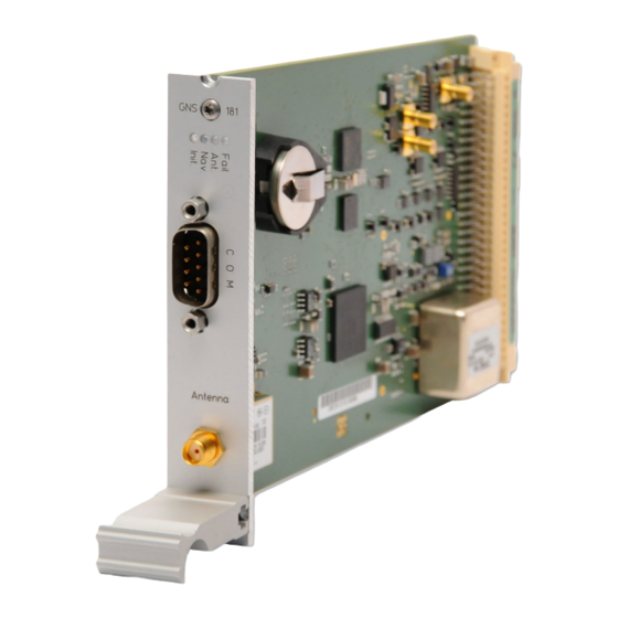
Page 10: Gnss Receiver
Nav. green: positioning successfully red: antenna faulty or not connected yellow: the clock is synchronized by an external Signal - MRS mode (PPS, IRIG ...) Fail red: time has not synchronized IMS-GNS181 Setup Guide Date: 20th March 2020... - Page 11 Pin 2: CS (Chip Select) Pin 3: MOSI (Master Out, Slave In) Pin 4: MISO (Master In, Slave Out) Pin 5: GND Attention: Use this plug only to connect a MEIN- BERG IMS-XHE Rubidium expansion chassis. Date: 20th March 2020 IMS-GNS181 Setup Guide...
-
Page 12: Configuration Of Ims Modules Via Web Interface
In case of a redundant receiver configuration the common settings for "IRIG In/Out", "Serial Ports", "Time Zone", "Enable Outputs", "Programmable Pulses" and "Synthesizers" appears into the "Switch Card" menu. Figure: Menu "Clock" in case of a single receiver IMS-GNS181 Setup Guide Date: 20th March 2020... - Page 13 Displays a hard time jump of the reference source (currently only available for PTP). Auto-Bias Time offset determined for the source versus an offset-free time source. Figure: An example of available reference signals in the priority order. Date: 20th March 2020 IMS-GNS181 Setup Guide...
- Page 14 Here is an example how to configure a priority list in a descending order: 1. Source: GNSS / GPS 2. PPS + String 3. PTP – IEEE1588 4. external NTP Server Figure: Configuration example of reference signals in a descending order. IMS-GNS181 Setup Guide Date: 20th March 2020...
- Page 15 - GPS / GNSS as the first priority has the highest estimated precision :100 ns - ext. Osc. (e.g. Rubidium): 120 ns - PTP IEEE 1588: 100 ns - PPS plus string: 100 ns - NTP: 100 us Date: 20th March 2020 IMS-GNS181 Setup Guide...
- Page 16 The MRS system should only use a PTP master to synchronize the clock if the desired clock class is given. It should be prevented that the slave remains synchronized to a bad master, although another source is available. IMS-GNS181 Setup Guide Date: 20th March 2020...
- Page 17 The Trusted Source (TRS) feature is a powerful tool to protect the GNSS receiver from spoofing attacks. For the moment, the Trusted Source feature is supported only in combination with a Meinberg GPS or GNSS receiver and a Meinberg XHE external Rubidium holdover unit.
- Page 18 With activated "Asymmetry Step Detection", the system measures the offset for approx. 10 minutes. After another 10 minutes, a determined value or offset is set, which is then displayed under MRS -> PTP status [Step Compensated]: Auto-Bias: 0.000000000s Step-Comp.: -0.000010001s Span: 0.000000025s IMS-GNS181 Setup Guide Date: 20th March 2020...
- Page 19 Here you can configure a limit value. If the reference source exceeds this limit, a notification is triggered. A configuration in the Web Interface is required on the Notification page "Notification Notofication Event XMR Limit Exceed". Figure: Configuration dialog for known offsets and limits. Date: 20th March 2020 IMS-GNS181 Setup Guide...
- Page 20 Time Scale: The output of the selected time code can be done with UTC or the local time. When "LOCAL TIME" is used, it refers to the configuration of the menu point "Time zone". IMS-GNS181 Setup Guide Date: 20th March 2020...
- Page 21 String Type: Meinberg Standard, SAT, NMEA RMC, Uni Erlangen, Computime, Sysplex 1, Meinberg Capture, SPA, RACAL, Meinberg GPS, NMEA GGA, NMEA RMC GGA, NMEA ZDA, ION, 6021, IRIG-J Mode: You can configure an interval (per second, per minute, on request "?" Only) for the outgoing time string.
- Page 22 4.1.1.11 Enabling the Outputs Optionally, the outputs of the reference clock can be set to always supply a signal when the device is switched on, or only when the internal clock is running synchronously. IMS-GNS181 Setup Guide Date: 20th March 2020...
- Page 23 Holdover mode: when the checkbox is activated. Note: In the clock-submenu "Enabling the Outputs" the Pulses option "if sync" must be select so that the outputs can be switched off in holdover mode. Date: 20th March 2020 IMS-GNS181 Setup Guide...
- Page 24 0.1. When the phase angle is increased, the delay of the output signal gets bigger. If a frequency higher than 10 kHz has been set, the phase cannot be changed. IMS-GNS181 Setup Guide Date: 20th March 2020...
- Page 25 5ns/m when using RG58U and 4ns/m when using H155 antenna cable. This time error is automatically compensated by entering the cable length. The default value is 20m. The maximum input value should not exceed 500m. Date: 20th March 2020 IMS-GNS181 Setup Guide...
- Page 26 GNM-Receiver ————————————————————————————————————————- GPS only GPS only GLONASS only Galileo only GLONASS Galileo only GPS/Galileo Galileo BeiDou only BeiDou GPS/GLONASS (All available systems can GPS/Galileo be received simultaneously) GPS/BeiDou Galileo/GLONASS Galileo/BeiDou GLONASS/BeiDou GPS/Galileo/GLONASS GPS/Galileo/BeiDou IMS-GNS181 Setup Guide Date: 20th March 2020...
- Page 27 "initialize Position". This option is useful when the system is operated at a different location and if started with the previously battery-buffered satellite data. Time/Date: With this function, the reference clock can manually be set to a specific date and time. Date: 20th March 2020 IMS-GNS181 Setup Guide...
- Page 28 So the number of good satellites can never exceed the number of satellites in view, but it can be signifi- cantly less if the antenna has been installed in a location with limited view to the sky. In worst case this can lead to limited accuracy, or only temporary synchronization. IMS-GNS181 Setup Guide Date: 20th March 2020...
- Page 29 4.1.1.17 Switch Card The RSC (SCU) switch card is an automatic multiplexer for redundant systems with two Meinberg radio clocks. The card is used for the automatic switching of the pulse and frequency outputs as well as the serial interfaces of the connected clocks.
-
Page 30: Front Display - Root Menu
When pressing the „OK“ button from main menu the version of the LANTIME software, the NTP and the LINUX kernel version will be displayed. ELX800 VX.XXx SN: 000000000000 NTP: X.X.Xx@X.X Krn.: X.X.XX.X IMS-GNS181 Setup Guide Date: 20th March 2020... - Page 31 System System System -> Setup MRS <- ->external NTP<- ->Interfaces <- ->Time Zone <- Info REFCLK Local Strat. Global Cfg. Restart Menu Setup REFCLK Restart NTP Services Factory Reset Set Outputs PTP IEEE1588 Date: 20th March 2020 IMS-GNS181 Setup Guide...
-
Page 32: Menu: Reference Time
Clock IRIG Receiver The Reference Clock menu and all its sub menus will manage all status information and parameters of the reference clock. To enter the following sub menus press the "OK" button. IMS-GNS181 Setup Guide Date: 20th March 2020... - Page 33 SCU card must be locked in position "Auto". Otherwise (position "Manual") the selected clock can only be changed by using the switch of the SCU. Date: 20th March 2020 IMS-GNS181 Setup Guide...
- Page 34 0 the time for switching to the next reference (hold over time) will be calculated by the following formula: (precision of next reference) / (precision of current master) * constant [s] The parameter „constant“ depends on the quality of the internal oscillator. IMS-GNS181 Setup Guide Date: 20th March 2020...
- Page 35 Set MRS & Info >Show IRIG Info< Offs.UTC: +00:00 > IRIG Receiver < Setup IRIG State: -------- IRIG Set IRIG Params Receiver B122/B123 Show IRIG Info Offset from UTC: > Setup IRIG < (+HH:MM) +00:00 Date: 20th March 2020 IMS-GNS181 Setup Guide...
- Page 36 CLK Satellites In this menu all relevant information about the reference clock, the internal oscillator and in case of a GNSS receiver, the visible and good satellites will be shown in the display. IMS-GNS181 Setup Guide Date: 20th March 2020...
- Page 37 IRIG-signal, only used with IEEE 1344) and the current system configuration is shown on the third line. On the fourth line the AGC (Automatic Gain Control of the input signal) value in hexadecimal will be shown. Date: 20th March 2020 IMS-GNS181 Setup Guide...
- Page 38 ‘lock on’ is set the first time. The ‘pulses enabled’ bit is set if the PPS signal is enabled. IRIG system configuration Bit 2 ... 0 Bit 7 ... 4: reserved Bit 3: ignore Day Of Year enabled Bit 2: ignore TFOM Bit 1: ignore SYNC Bit 0: IEEE 1344 enabled IMS-GNS181 Setup Guide Date: 20th March 2020...
- Page 39 4.1.3.7 Menu: Setup Meinberg Receiver GPS / GLONASS (CLK) Setup MRS >Antenna Length< Info REFCLK Simulation Mode ->Setup REFCLK<- Init CLK Set Outputs Info > Trans.Distance < ->Setup PZF <- Init Time Serial Outputs Ignore Lock WWVB, MSF, JJY ...
- Page 40 Warm Boot mode, otherwise the system changes into Cold Boot to read new data. Antenna Lengt GNSS Cold Boo INITIATE Simulation Mo -> GNSS Warm Boo WARM BOOT ->Init GNSS Set Position OF GNSS RECEIV Set GNSS Time Press F2! IMS-GNS181 Setup Guide Date: 20th March 2020...
- Page 41 In this case the menu Simulation Mode has to be active. After setting the clock manually the system time will be set and the NTP will be restarted. Antenna Lengt GNSS Cold Boo SET INITIAL TI Simulation Mo GNSS Warm Boo ->Init GNSS Set Position Time: 12:38:09 ->Set GNSS Time Date: 29.11.20 Date: 20th March 2020 IMS-GNS181 Setup Guide...
- Page 42 The default setting for all outputs is ’if Sync’. Time Zone: See Chapter "Set Time Zone of Serial Outputs". IMS-GNS181 Setup Guide Date: 20th March 2020...
- Page 43 • Sysplex 1 • Meinberg Capture • SPA • RACAL • Meinberg GPS • NMEA GGA (Rev. 2.2) • NMEA RMC GGA (Rev. 2.2) • NMEA ZDA (Rev. 2.2) • ION • 6021 • IRIG-J Date: 20th March 2020 IMS-GNS181 Setup Guide...
- Page 44 If no changeover in daylight saving is wanted, identical dates and times must be entered in both of the submenus (DAYLIGHT SAV ON/OFF). After this a restart should be done. IMS-GNS181 Setup Guide Date: 20th March 2020...
- Page 45 "TIME: Local". The following codes can be selected: • IRIG B002+B122 • IRIG B006+B126 • IRIG B007+B127 • AFNOR NF S87-500 • C37.M8 • IEEE1344 Refer to chapter Timecode for details. Date: 20th March 2020 IMS-GNS181 Setup Guide...
- Page 46 DCF77. The generated time code is related to the local time zone. If you want DCF simulation to be disabled when the clock is in free running mode, you can enter the delay (given in minutes) for deactivat- IMS-GNS181 Setup Guide Date: 20th March 2020...
- Page 47 Idle Mode Selecting "Idle" deactivates the output. Holdover If "enabled" is selected the operation of the output remains. Otherwise ("disabled") the operation of the output will be switched off when synchronization is lost. Date: 20th March 2020 IMS-GNS181 Setup Guide...
- Page 48 0.1 . Increasing the phase lets the signal come out later. Phase affects frequencies less than 10.00 kHz only, if a higher frequency is selected a message "(phase ignored)" informs the user that the phase value is ignored. IMS-GNS181 Setup Guide Date: 20th March 2020...
-
Page 49: General Gnss Antennae
Some Meinberg devices use alternate GNSS receivers which support other satellite systems like GLONASS, Galileo or BeiDou, in addition to GPS. These receivers can’t be operated directly with the standard Meinberg antenna/converter unit described in chapter "Meinberg GPS Receiver", so they require a different kind of antenna. - Page 50 - Do not carry out any work on the antenna system or the antenna cable if there is a risk of a lightning strike. - Do not carry out any work on the antenna system if the safety distance to free lines and sequential circuits is exceeded. IMS-GNS181 Setup Guide Date: 20th March 2020...
-
Page 51: Gnss Antenna For Mobile Applications
- Do not carry out any work on the antenna system or the antenna cable if there is a risk of a lightning strike. - Do not carry out any work on the antenna system if the safety distance to free lines and sequential circuits is exceeded. Date: 20th March 2020 IMS-GNS181 Setup Guide... -
Page 52: Powering Up A Gnss Receiver
GPS Satellites") as well as via the Web GUI ("Clock Receiver Information") you can check the number of satellites that are in view (i.e. above the horizon) and considered good (i.e. are healthy and can be tracked). IMS-GNS181 Setup Guide Date: 20th March 2020...
Need help?
Do you have a question about the IMS-GNS181 and is the answer not in the manual?
Questions and answers