Ingersoll-Rand QA1L Series Maintenance Information
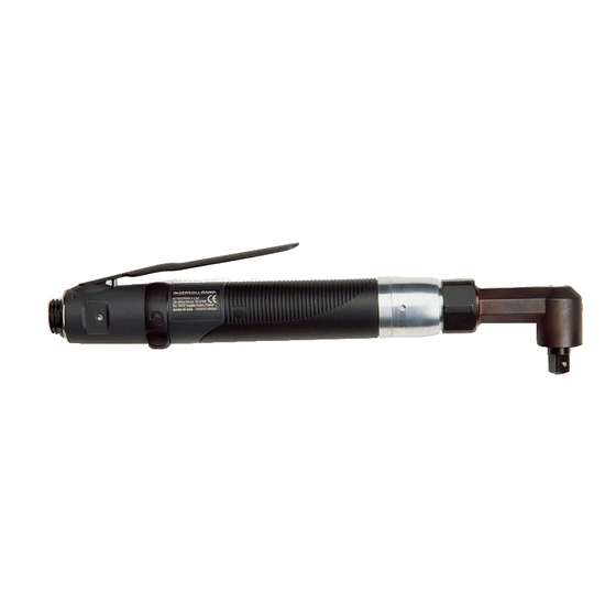
Reversible angle screwdrivers and angle wrenches
Hide thumbs
Also See for QA1L Series:
- Product information (84 pages) ,
- Operation and maintenance manual (35 pages) ,
- Maintenance information (12 pages)

Subscribe to Our Youtube Channel
Related Manuals for Ingersoll-Rand QA1L Series


Summary of Contents for Ingersoll-Rand QA1L Series
- Page 1 16575201 Edition 2 December 2013 Reversible Angle Screwdrivers and Angle Wrenches Series QA1L Maintenance Information Save These Instructions...
-
Page 2: Product Safety Information
Product Safety Information WARNING • Failure to observe the following warnings, and to avoid these potentially hazardous situations, could result in death or serious injury. • Read and understand this and all other supplied manuals before installing, operating, repairing, maintaining, changing accessories on, or working near this product. - Page 3 NOTICE The Clutch Housing has a left-hand thread. Rotate the Housing clockwise to loosen it. g. Engage the hook of the Clutch Housing Spanner Wrench (Part No. TRH-478) in the adjustment slot in the Gear Case and loosen the Clutch Housing. h.
- Page 4 10. For TRL1S4 Angle Heads, to remove the Spindle Upper Bearing Shaft (116), stand the gear end of the Spindle on a block with clearance for the Shaft. Insert a 1/8” round rod into the detent retainer opening and using an arbor press, press the Shaft out of the Spindle. 11.
- Page 5 5. Invert the Gear Case on the table of an arbor press so that the end face having four notches makes contact with the table. Using a rod against the inner race of the Spindle Bearing, press the Bearing from the Gear Case. 6.
- Page 6 Measurement of Front End Plate Clearance (Dwg. TPA1740) 4. Wipe each Vane (29) with a light film of Ingersoll Rand No.10 Oil and place a Vane in each slot in the Rotor. 5. One end of the Cylinder Assembly (25) has a notch that breaks the outer wall and end face of the Cylinder. With that end trailing, install the Cylinder Assembly over the Rotor and Vanes against the Front End Plate.
- Page 7 Assembly of the Adjustable Shutoff Clutch 1. Hold the Clutch Shaft (52) in your hand with the large end upward. 2. Insert the Automatic Shutoff Plunger Return Spring (49) into the central opening in the large end of the Clutch Shaft. Use a 1/8” dowel to push the Spring below the cross hole for the Automatic Shutoff Pin (50).
- Page 8 8. Use the 9/16” hex stock with clearance for the bevel pinion shaft that was used during disassembly to screw the Angle Head Plug (106) into the Angle Head against Pinion Rear Bearing. Tighten the Plug between 8 and 12 ft-lbs. (10.8 and 16.2 Nm) torque. 9.
-
Page 9: Testing The Tool
17. Using needle nose pliers, insert the Throttle Valve (14), long stem leading, into the opening against the Seat. Center the Valve in the Seat. 18. Install the Throttle Valve Spring (15) in the opening so that it encircles the Valve. 19. -
Page 10: Troubleshooting Guide
Troubleshooting Guide Trouble Probable Cause Solution Loss of Power Low air pressure Check air supply. For top performance, the air pressure must be 90 psig (6.2 bar/620 kPa) at the inlet. Plugged Inlet Bushing Screen Clean the Inlet Bushing Screen using a clean, suit-able cleaning solution. If the Screen cannot be cleaned, replace it. - Page 11 Notes:...
- Page 12 ingersollrandproducts.com © 2013 Ingersoll Rand...
Need help?
Do you have a question about the QA1L Series and is the answer not in the manual?
Questions and answers