Ingersoll-Rand QA1L Series Operation And Maintenance Manual
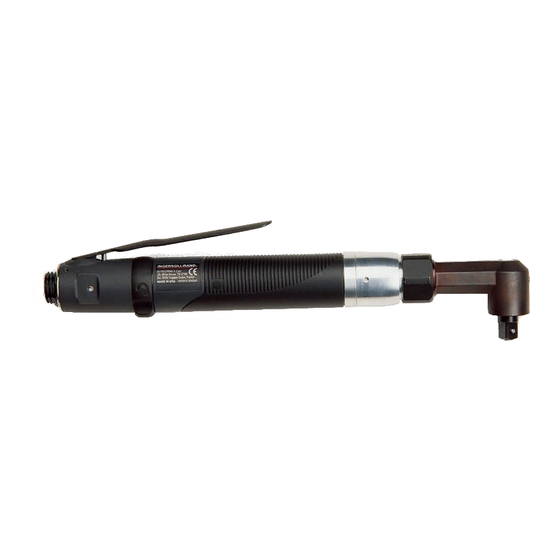
High torque reversible angle screwdrivers and angle wrenches
Hide thumbs
Also See for QA1L Series:
- Product information (84 pages) ,
- Maintenance information (12 pages) ,
- Product information (80 pages)
Table of Contents
Advertisement
Quick Links
OPERATION AND MAINTENANCE MANUAL
FOR SERIES QA1L HIGH TORQUE REVERSIBLE
ANGLE SCREWDRIVERS AND ANGLE WRENCHES
Series QA1L Angle Screwdrivers and Angle Wrenches are designed for running small threaded
fasteners in close–quarter applications.
Ingersoll–Rand is not responsible for customer modification of tools for applications on which
Ingersoll–Rand was not consulted.
IT IS THE RESPONSIBILITY OF THE EMPLOYER TO PLACE THE INFORMATION
IN THIS MANUAL INTO THE HANDS OF THE OPERATOR.
FAILURE TO OBSERVE THE FOLLOWING WARNINGS COULD RESULT IN INJURY.
PLACING TOOL IN SERVICE
•
Always operate, inspect and maintain this tool in
accordance with American National Standards
Institute Safety Code for Portable Air Tools
(ANSI B186.1).
•
For safety, top performance, and maximum
durability of parts, operate this tool at 90 psig (6.2
bar/620 kPa) maximum air pressure at the inlet
with 1/4" (6 mm) inside diameter air supply hose.
•
Always turn off the air supply and disconnect the
air supply hose before installing, removing or
adjusting any accessory on this tool, or before
performing any maintenance on this tool.
•
Do not use damaged, frayed or deteriorated air
hoses and fittings.
•
Be sure all hoses and fittings are the correct size
and are tightly secured. See Dwg. TPD905–1 for a
typical piping arrangement.
•
Always use clean, dry air at 90 psig (6.2 bar/620
kPa) maximum air pressure. Dust, corrosive fumes
and/or excessive moisture can ruin the motor of an
air tool.
•
Do not lubricate tools with flammable or volatile
liquids such as kerosene, diesel or jet fuel.
•
Do not remove any labels. Replace any damaged
label.
The use of other than genuine Ingersoll–Rand replacement parts may result in safety hazards, decreased tool
performance, and increased maintenance, and may invalidate all warranties.
Repairs should be made only by authorized trained personnel. Consult your nearest Ingersoll–Rand Authorized
Servicenter.
Refer All Communications to the Nearest
Ingersoll–Rand Office or Distributor.
Ingersoll–Rand Company 2000
Printed in U.S.A.
IMPORTANT SAFETY INFORMATION ENCLOSED.
READ THIS MANUAL BEFORE OPERATING TOOL.
04577383
USING THE TOOL
•
Always wear eye protection when operating or
performing maintenance on this tool.
•
Always wear hearing protection when operating
this tool.
•
Keep hands, loose clothing and long hair away from
rotating end of tool.
•
Note the position of the reversing lever before
operating the tool so as to be aware of the direction
of rotation when operating the throttle.
•
Anticipate and be alert for sudden changes in
motion during start up and operation of any power
tool.
•
Keep body stance balanced and firm. Do not
overreach when operating this tool. High reaction
torques can occur at or below the recommended air
pressure.
•
Tool accessory may continue to rotate briefly after
throttle is released.
•
Air powered tools can vibrate in use. Vibration,
repetitive motions or uncomfortable positions may
be harmful to your hands and arms. Stop using any
tool if discomfort, tingling feeling or pain occurs.
Seek medical advice before resuming use.
•
Use accessories recommended by Ingersoll–Rand.
•
This tool is not insulated against electric shock.
•
This tool is not designed for working in explosive
atmospheres.
F
Form P7465
Edition 2
E
December, 2000
P
Advertisement
Table of Contents

Related Manuals for Ingersoll-Rand QA1L Series


Summary of Contents for Ingersoll-Rand QA1L Series
- Page 1 04577383 Form P7465 Edition 2 December, 2000 OPERATION AND MAINTENANCE MANUAL FOR SERIES QA1L HIGH TORQUE REVERSIBLE ANGLE SCREWDRIVERS AND ANGLE WRENCHES Series QA1L Angle Screwdrivers and Angle Wrenches are designed for running small threaded fasteners in close–quarter applications. Ingersoll–Rand is not responsible for customer modification of tools for applications on which Ingersoll–Rand was not consulted.
-
Page 2: Warning Label Identification
WARNING LABEL IDENTIFICATION FAILURE TO OBSERVE THE FOLLOWING WARNINGS COULD RESULT IN INJURY. WARNING WARNING WARNING Always turn off the air sup- Always wear eye protection Always wear hearing ply and disconnect the air when operating or perform- protection when operating supply hose before install- ing maintenance on this this tool. - Page 3 PLACING TOOL IN SERVICE LUBRICATION MAIN LINES 3 TIMES AIR TOOL INLET SIZE Ingersoll–Rand No. 10 Gearing: SYSTEM Ingersoll–Rand No. 67 Clutch: Ingersoll–Rand No. 28 TOOL Always use an air line lubricator with this tool. LUBRICATOR We recommend the following Filter–Lubricator–Regulator FILTER REGULATOR Unit:...
-
Page 4: Model Identification
MODEL IDENTIFICATION Tool Rotation Throttle Free Clutch Bit Holder Angle Head Accessory Style Speed or Driver QA (Angle) 1 (Reversible) L (Lever Start) 05 (0500) (Automatic (1/4” Quick Release) XL (Large) D (Memory Chip) 02 (0250) Shut–off) (3/8” Square Drive) B (1/4–19 BSPT (Cushion Clutch) (1/4”... -
Page 5: Utilisation De L'outil
• Ne jamais lubrifier les outils avec des liquides • Utiliser les accessoires recommandés par inflammables ou volatiles tels que le kérosène, le gasol Ingersoll-Rand. ou le carburant d’aviation. • Cet outil n’est pas conçu pour fonctionner dans des •... - Page 6 SIGNIFICATION DES ETIQUETTES D’AVERTISSEMENT ATTENTION LE NON RESPECT DES AVERTISSEMENTS SUIVANTS PEUT CAUSER DES BLESSURES ATTENTION ATTENTION ATTENTION Couper toujours l’alimentation Porter toujours une Porter toujours des lunettes d’air comprimé et débrancher le protection acoustique de protection pendant flexible d’alimentation avant pendant l’utilisation de cet l’utilisation et l’entretien de d’installer, déposer ou ajuster...
-
Page 7: Mise En Service De L'outil
MISE EN SERVICE DE L’OUTIL LUBRIFICATION Tous les 40.000 cycles ou au moins tous les mois, selon le cas, injecter 2 à 4 cm# de graisse Ingersoll–Rand No. 67 dans le raccord de graissage du renvoi d’angle. TUYAUTERIE PRINCIPALE AU MOINS 3 FOIS LA DIMENSION DE Ingersoll–Rand No. - Page 8 IDENTIFICATION DES MODÈLES Style Rotation Commande Vitesse Limiteur Porte–embout Renvoi d’angle Accessoire d’outil à vide ou entraîneur QA (Angle) 1 (Réversible) L (Démarrage 05 (0500) S (Arrêt 1 (1/4” Changement rapide) XL (Large) D (Puce mémoire) 02 (0250) automatique) 6 (Carré Entraîneur 3/8”) B (1/4–19 BSPT gâchette) C (Limiteur...
- Page 9 MANUAL DE USO Y MANTENIMIENTO PARA LLAVES ANGULARES Y ATORNILLADORES ANGULARES REVERSIBLES DE ELEVADO PAR DE LA SERIE QA1L NOTA Las Llaves Angulares y Atornilladores Angulares Serie QA1L están diseñadas para el atornillado de pequeñas uniones roscadas en aplicaciones de acceso reducido. Ingersoll–Rand no aceptará...
-
Page 10: Etiquetas De Aviso
ETIQUETAS DE AVISO AVISO EL HACER CASO OMISO DE LOS AVISOS SIGUIENTES PODRIA OCASIONAR LESIONES. ADVERTENCIA ADVERTENCIA ADVERTENCIA Cortar siempre el suministro Use siempre protección ocular de aire y desconectar la man- Use siempre protección para guera de suministro de aire cuando utilice esta herramienta los oídos cuando utilice esta o realice operaciones de... - Page 11 PARA PONER LA HERRAMIENTA EN SERVICIO LUBRICACION TUBERÍAS PRINCIPALES 3 VECES EL TAMAÑO DE ENTRADA DE HERRAMIENTA A SISTEMA NEUMÁTICA NEUMÁTICO Ingersoll–Rand Nº 10 Engranajes: Ingersoll–Rand Nº 67 Embrague: Ingersoll–Rand Nº 28 HERRA– Utilice siempre un lubricador de aire comprimido con estas MIENTA llaves de impacto.
-
Page 12: Identificación De Modelos
IDENTIFICACIÓN DE MODELOS Estilo de Rotación Palanca Velocidad Embrague Portapuntas Cabeza Accesorio herramienta de mando en vacío o cuadradrillo Angular QA (Angular) 1 (Reversible) L (Arranque 05 (0500) S (Parada 1 (de cambio rápido 1/4”) XL (Grande) D (Chip de memoria) por Palanca) 02 (0250) automática) - Page 13 MANUAL DE FUNCIONAMENTO E MANUTENÇÃO PARA APARAFUSADORAS E CHAVES INGLESAS EM ÂNGULO REVERSÍVEIS DE BINÁRIO ELEVADO SÉRIE QA1L AVISO As Aparafusadoras e Ferramentas Pneumáticas Angulares Séries QA1L são concebidas para accionar apertadores de rosca pequenos em aplicações em espaços reduzidos. A Ingersoll–Rand não é...
- Page 14 IDENTIFICAÇÃO DO RÓTULO DE ADVERTÊNCIA ADVERTÊNCIA O NÃO CUMPRIMENTO DAS SEGUINTES ADVERTÊNCIAS PODE RESULTAR EM FERIMENTO. ADVERTÊNCIA ADVERTÊNCIA ADVERTÊNCIA Desligue sempre a alimentação de Use sempre óculos de pro- Use sempre protecção contra ar e desconecte a mangueira de tecção quando estiver ope– alimentação de ar antes de insta- o ruído ao operar esta ferra- rando ou executando algum...
- Page 15 COLOCANDO A FERRAMENTA EM FUNCIONAMENTO LUBRIFICAÇÃO LINHAS PRINCIPAIS 3 VEZES O TAMANHO DA ENTRADA DA FERRAMENTA PNEUMÁTICA PARA SISTEMA DE AR Ingersoll–Rand No. 10 Engrenagem: Ingersoll–Rand No. 67 Embraiagem: PARA Ingersoll–Rand No. 28 FERRAMENTA PNEUMÁTICA Use sempre um lubrificador de ar de linha com estas ferramentas.
- Page 16 MODEL IDENTIFICATION Estilo Rotação Estrangulador Velocidade Embraiagem Porta–brocas Cabeça em Acessório da ferramenta livre ou accionador Ângulo QA (Ângulo) 1 (Reversível) L (Arranque por 05 (0500) (Desligamento (Libertação rápida de 1/4”) XL (Grande) D (Chip de Alavanca) 02 (0250) automático) (Accionamento quadrado memória) (Embraiagem...
- Page 17 SERIES QA1L HIGH TORQUE ANGLE FASTENER MOTOR AND GEARING (Dwg. TPA1825)
- Page 18 SERIES QA1L HIGH TORQUE ANGLE FASTENER MOTOR AND GEARING PART NUMBER FOR ORDERING PART NUMBER FOR ORDERING Motor Housing ......TRL–40 Cylinder Rear Alignment Pin .
- Page 19 SERIES QA1L HIGH TORQUE ANGLE FASTENER CLUTCHES (Dwg. TPA1826)
- Page 20 SERIES QA1L HIGH TORQUE ANGLE FASTENER CLUTCHES PART NUMBER FOR ORDERING PART NUMBER FOR ORDERING Automatic Shutoff Clutch Assembly Cushion Clutch Assembly with medium clutch spring (standard) . . . TRH–AM579 with medium clutch spring (standard) . . . TRH–AM579–C with light clutch spring .
- Page 21 SERIES QA1L HIGH TORQUE GRIP, GEARING AND ANGLE ATTACHMENTS (TDwg. TPA1827)
- Page 22 SERIES QA1L HIGH TORQUE GRIP, GEARING AND ANGLE ATTACHMENTS PART NUMBER FOR ORDERING PART NUMBER FOR ORDERING Clutch Housing ......TRL–580 Coupling Nut .
-
Page 23: Speed Adjustment
CLUTCH SPRING SELECTION CHART TORQUE RANGE (Soft Draw) Light Clutch Spring Medium Clutch Spring Tool Free Speed (Yellow) (Red) (rpm) All Series QA High Torque Angle 11.7 to 38.2 in–lbs. 31.0 to 88.3 in–lbs. Screwdrivers and Angle (1.32 to 4.32 Nm) (3.50 to 9.98 Nm) Wrenches 11.7 to 38.2 in–lbs. - Page 24 MAINTENANCE SECTION The Coupling Nut has a left–hand thread. Rotate The Clutch Housing has a left–hand thread. the Nut clockwise to loosen it. Rotate the Housing clockwise to loosen it. Using a wrench on the flats of the Coupling Nut, 13.
- Page 25 MAINTENANCE SECTION Disassembly of the Angle Head Slide the Coupling Nut (104) toward the output end The thread in the following step is a left–hand of the Angle Head (100) and using a thin blade thread. Rotate the wrench clockwise to remove screwdriver, work the Coupling Nut Retaining Ring the Cap.
- Page 26 MAINTENANCE SECTION Insert the tip of a #1 Phillips Head Screwdriver into the adjustment opening between the Clutch Adjusting Nut (79) and the Clutch Adjusting Nut Washer (78). Rotate the screwdriver clockwise to thread the In the following step, the Clutch Cam Balls will be Adjustment Nut off the Clutch Shaft.
- Page 27 MAINTENANCE SECTION Stand the Rear Gear Case or the Front Gear Case (87) Whenever grasping a tool or part in a vise, always use on the table of an arbor press with the output spindle leather–covered or copper–covered vise jaws to upward.
- Page 28 MAINTENANCE SECTION Using snap ring pliers, install the Rear End Plate Assembly Retainer (24) in the annular groove on the rear rotor hub to secure the assembly in position. In the following step, the measurement must be Set the assembled motor aside. made at the end corner of the large rotor body.
- Page 29 MAINTENANCE SECTION Lay a bead of Ingersoll–Rand No. 28 Grease, Spring. The smaller center portion of the Shutoff approximately 2 to 3 cc, on top of the Clutch Balls Plunger will allow the Shutoff Pin to spring outward and then bring the Clutch Shaft and Cam Jaw and capture the components within the Clutch Shaft together capturing the Balls between them.
- Page 30 MAINTENANCE SECTION Invert the Front Gear Case and using another piece of 12. Insert the assembled Spindle, output end trailing, into tubing that supports the inner race of the Bearing and the Angle Head. clears the output end of the Spindle Assembly, press the Intermediate Spindle Assembly into the Bearing from the clutch end of the Front Gear Case.
- Page 31 MAINTENANCE SECTION Place the narrow end of the Clutch Return Spring (46 16. Being careful not to damage it, insert the Throttle or 65) in the Rear Gear Case against the inner race of Valve Seat (13) into the central opening at the inlet the Spindle Bearing (44).
-
Page 32: Testing The Tool
MAINTENANCE SECTION TESTING THE TOOL Before placing the tool back in service, test the tool in a The thread in the following step is a left–hand run down application to determine if adjustments are thread. Rotate the Nut counterclockwise to necessary to satisfactorily perform the operation. -
Page 33: Troubleshooting Guide
TROUBLESHOOTING GUIDE Trouble Probable Cause Solution Loss of Power Low air pressure Check air supply. For top performance, the air pressure must be 90 psig (6.2 bar/620 kPa) at the inlet. Plugged Inlet Bushing Screen Clean the Inlet Bushing Screen using a clean, suit- able cleaning solution.
Need help?
Do you have a question about the QA1L Series and is the answer not in the manual?
Questions and answers