
Subscribe to Our Youtube Channel
Related Manuals for Ingersoll-Rand QP1P Series


Summary of Contents for Ingersoll-Rand QP1P Series
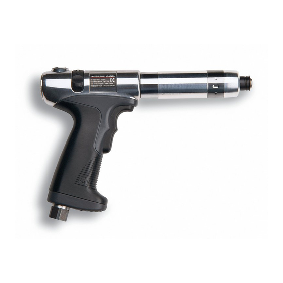
- Page 1 16575219 Edition 4 October 2013 Air Screwdrivers QP1P, QP1S and QP1T Series Maintenance Information Save These Instructions...
- Page 2 Product Safety Information WARNING • Failure to observe the following warnings, and to avoid these potentially hazardous situations, could result in death or serious injury. • Read and understand this and all other supplied manuals before installing, operating, repairing, maintaining, changing accessories on, or working near this product.
- Page 3 8. Using a hooked tool, reach into the opening in the end of the NOTICE Clutch Shaft and carefully pull the Automatic Shutoff Plunger Return Spring (63) out of the Shaft without elongating the Spring. The thread in the following step is a left-hand thread. Rotate the Disassembly of the Adjustable Cushion Clutch Clutch Housing clockwise to remove it.
- Page 4 Disassembly of the Motor 7. For Models with Trigger Start or Trigger Permit, remove the Throttle Valve Spring (19) and the Throttle Valve (18) from the 1. Using snap ring pliers, remove the Rear End Plate Assembly rear of the Housing. Retainer (33) from the shaft of the Rotor (37).
- Page 5 17. Install the Housing Grip (21) over the Elements and onto the inlet 8. Using snap ring pliers, install the Rear End Plate Assembly end of the Motor Housing. Make certain the Grip is fully seated Retainer (33) in the annular groove on the rear rotor hub to against the Housing and the Trigger Assembly works freely.
- Page 6 10. Insert the tip of a #1 Phillips Head Screwdriver into the 2. Lubricate the Motor Seal (42) with O-Ring lubricant and install adjustment opening between the Clutch Adjusting Nut and it around the Front End Plate (39) and into the undercut in the the Clutch Adjusting Nut Washer.
- Page 7 Testing the Tool NOTICE Before placing the tool back in service, test the tool in a run down application to determine if adjustments are necessary to satisfactorily The following step has threads with a left-hand thread. Rotate perform the operation. Since four interrelated adjustments can affect the components counterclockwise to tighten them.
- Page 8 ingersollrandproducts.com © 2013 Ingersoll Rand...
Need help?
Do you have a question about the QP1P Series and is the answer not in the manual?
Questions and answers