Table of Contents
Advertisement
Quick Links
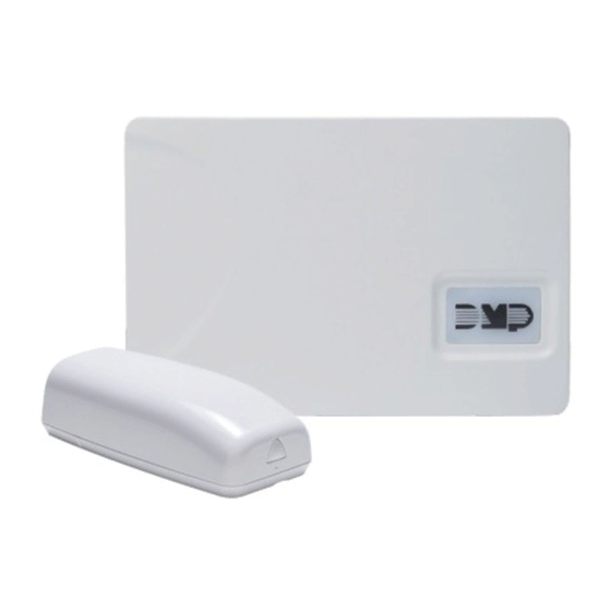
1100X SERIES WIRELESS RECEIVER
Installation Guide
WALL
TAMPER
ENABLE
DISABLE
Figure 1: 1100X Series
Wireless Recever
DESCRIPTION
The 1100X Series Wireless Receiver
provides up to 100 wireless zones
for XR150 Series panels and up
to 500 wireless zones for XR550
Series panels. The 1100XE features
128-bit AES encryption.
The 1100X also provides two-way
communication using 900 MHz
frequency hopping-spread-
spectrum technology.
The 1100X is equipped with a case
and wall tamper.
Compatibility
•
XR150/XR550 Series Panels
•
Encryption requires panel
Version 183 or higher
•
1100T Translator requires
receiver firmware Version
207/301 or higher
What is Included?
•
1100X Wireless Receiver
•
Model 300 Harness
•
Hardware Pack
1
PROGRAM THE PANEL
Refer to the panel programming guide as needed.
RF RX
RF TX
PANEL RX
PANEL TX
STATUS
PWR
2
SELECT A LOCATION
The receiver should be centrally located between the DMP panel
and the 1100 Series transmitters used in the installation based
on the wiring specifications below. Use an 1106 Series Universal
Wireless Transmitter to perform an LED survey.
3
MOUNT THE 1100X
1.
Reset the panel.
2.
At a keypad, enter 6653 (PROG) to access the
PROGRAMMER menu.
3.
In SYSTEM OPTIONS, program a HOUSE CODE between
1 and 50. See House Code Explained for more information.
(1100XE only) At the 1100 ENCRYPTION prompt, select
4.
ALL to only add encrypted wireless devices to the system.
Select BOTH to allow both encrypted and non-encrypted
wireless devices to be programmed.
5.
(1100XE only) The default passphrase appears at
ENTER PASSPHRASE. Press CMD to keep the default. Press
any select key or area to change the passphrase and enter
an 8-character hexadecimal string (0-9, A-F).
Press CMD until STOP displays. Press a top row select key
6.
or area to save programming.
1.
With the cover removed, hold the transmitter in the desired
location.
2.
Press the tamper switch to send data to the panel and
determine if communication is confirmed or faulty.
Confirmed: If communication is confirmed, for each
press or release of the tamper switch, the LED blinks
immediately on and immediately off.
Faulty: If communication is faulty, the LED remains on
for about 8 seconds or flashes multiple times in quick
succession. Relocate the receiver until the LED confirms
clear communication.
1.
Remove the cover from the plastic housing.
2.
Use the included #6 screws to secure the 1100X to the wall.
See Figure 2 for mounting hole locations.
3.
Use one of the provided screws to secure the wall tamper.
See Figure 2 for tamper location.
Wall Tamper
Figure 2: Inside of the 1100X Housing
Tamper Puck
Mounting Hole
Advertisement
Table of Contents

Related Manuals for DMP Electronics 1100XE


Summary of Contents for DMP Electronics 1100XE
- Page 1 1 and 50. See House Code Explained for more information. PANEL RX PANEL TX (1100XE only) At the 1100 ENCRYPTION prompt, select STATUS ALL to only add encrypted wireless devices to the system. Select BOTH to allow both encrypted and non-encrypted wireless devices to be programmed.
- Page 2 WIRE THE RECEIVER The panel immediately recognizes the 1100X if the panel is programmed with a house code. Do not use shielded wire between the panel and receiver. Connect the red, yellow, green, and black wires to the PANEL terminal on the 1100X. Connect the other end of the wires to the XBUS on the panel.
- Page 3 1100X LED Operation INDICATIONS The six labeled LEDs on the 1100X PCB display wireless receiver operation RF RX Flashing yellow indicates and activity. See Table 2 for LED locations and Table 1 for LED indications. data is being received from a transmitter.
- Page 4 ANSI/UL 268 Smoke Detectors for Fire Alarm Signaling Ordering Information Systems 1100X-W Standard Wireless Receiver • ANSI/UL 634 Connections and Switches for use with Burglar 1100XE-W Encrypted Wireless Receiver Alarm Systems Accessory • ANSI/UL 636 Safety Holdup Alarm Units and Systems Certifications •...
Need help?
Do you have a question about the 1100XE and is the answer not in the manual?
Questions and answers