Table of Contents
Advertisement
Quick Links
Download this manual
See also:
Installation Manual
Advertisement
Table of Contents

Subscribe to Our Youtube Channel
Related Manuals for DMP Electronics SCS-1R


Summary of Contents for DMP Electronics SCS-1R
-
Page 1: Installation Guide
InstallatIon GuIde sCs-1R seCuRIty ContRol ReCeIveR DMP Receiver Help Line Technical Service 1-888-436-7832 International 1-417-831-9362 After hours receiver emergencies 1-417-831-2866... - Page 2 Security Control Receiver Model SCS-1R Installation Guide © 2003-2008 Digital Monitoring Products, Inc. Information furnished by DMP is believed to be accurate and reliable. This information is subject to change without notice.
-
Page 3: Table Of Contents
Network Connection .............. 4 AC Power ................4 Optional Printer ..............4 Start up ................4 Configuration ................ 4 Model SCS-1R Security Control Receiver Description ................5 SCS-1R Components Included ..........5 Model SCS-RACK System Enclosure Description ................6 Modem Rack ................. 6 Multibus Rack................ - Page 4 Model SCS-202 Convenience Panel Description ................14 Installation................14 Model SCS-204 Host Cable Description ................14 Installation................14 Host Cable ................14 SCS-1R Printer Cable Printer Cable Pinout ..............15 Security Control Terms Using the LCD Membrane Keypad Special Keys .................16 COMMAND Key ..............16 Back Arrow Key ..............16 Select Keys ...............16...
- Page 5 T able of ConTenTs SCS-1R Configuration and Programming Normal Operation Display .............19 Operator Signon ..............19 Set System Time/Day/Date ...........19 Operator Codes ..............20 Configure System ..............21 System Status ..............22 Host Automation ..............23 Exit Menu ................25 Printout Explanations General Description ..............26 System Messages ..............26 Operator Signon ..............26...
-
Page 6: Operator's Quick Reference
Press the key labeled ACK, or any top row Select key, to acknowledge an alarm. When the SCS-1R is in normal mode, the alarm message displays in the LCD display. If you are in programming when an alarm is received and requires acknowledgement, the ACK LED lights and the keypad begins to beep. -
Page 7: System Overview
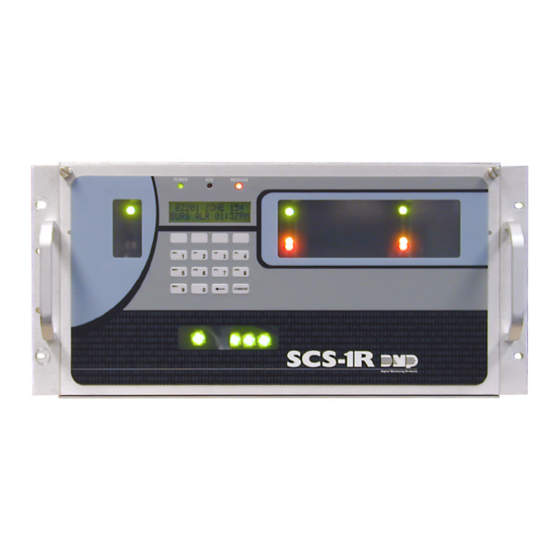
System Overview Description The SCS-1R Security Control Receiver system from DMP is a full featured digital dialer and data network capable alarm receiver. The receiver provides a 32-character LCD display for viewing incoming messages and a built-in membrane keypad for acknowledging messages and configuring the SCS-1R system. -
Page 8: System Block Diagram
Model SCS-100 Line Card Port 6 Line 5 Model SCS-101 Network Interface Card Model SCS-202 Convenience Panel 3-connector Ribbon Cable Model SCS-204 Host Cable Listed Printer or Membrane Automation Listed Capture Keypad and Computer Software 32-Character LCD Digital Monitoring Products SCS-1R Installation Guide... -
Page 9: Installation Checklist
To lower the SCS-1R faceplate, turn the two screws located in the top corners of the SCS-1R. The front of the SCS-1R opens on a hinge to allow access to the inside of the SCS-1R. Close the SCS-1R system by raising the front of the SCS-1R and securing the two screws in the top corners. - Page 10 Model SCS-1R Security Control Receiver Description The DMP SCS-1R Receiver ships from the factory with all of the necessary system components to provide two Digital Dialer lines and one line of Data Network receiving capability. This package can be expanded to include a maximum of five incoming communication lines.
-
Page 11: Rack Mounting
Rack Mounting The SCS-1R must be mounted in a standard 19” rack for listed Fire Signaling applications. Simply slide the entire unit into the 19” rack and secure with screws. Refer to the drawing below for rack-mounting hole locations. -
Page 12: Model Scs-1062 Processor Card
Jumper Settings Jumper Settings Jumper Settings Line 5 33, 36, 38, 40 34, 35, 38, 40 for Lines 1 and 2 for Lines 3 and 4 for Line 5 Figure 2: SCS-1062 Line Jumpers Digital Monitoring Products SCS-1R Installation Guide... - Page 13 SCS-1062 LEDs 1) Far Left LED: Flashes constantly. This is the watchdog, or heartbeat, LED. 2) Center Left LED: On when the SCS-1R is saving data, such as programming changes. 3) Not used. 4) Far Right LED: On when memory resources are low, such as messages pending for host automation or the printer.
-
Page 14: Connecting The Phone Line
On when a digital dialer line card has answered the phone line. Ring Detect On when ringing voltage is detected on phone line. Data Terminal Ready On when the line card is ready to receive. Digital Monitoring Products SCS-1R Installation Guide... -
Page 15: Model Scs-101 Network Interface Card
The SCS-101 line card Level E Version 200 or higher can ONLY be used with SCS-1R Receivers with firmware Version 903 or higher and is NOT compatible with the SCS-1 Receiver. The SCS-101 line card Level D Version 103 or lower can ONLY be used with the SCS-1R Version 902 or lower or SCS-1 Receivers. -
Page 16: Model Scs-110 Modem Power Supply Card
The SCS-110 provides power to a maximum of five line cards. Power is supplied through the modem rack backplane connectors without additional cabling. The SCS-110 also provides LCD and keypad connection, UPS system status, and the 120 VAC input monitoring information to the SCS-1R Receiver. Installing the SCS-110 Always remove power to the SCS-1R Receiver when installing or removing the SCS-110. -
Page 17: Model Scs-120 Multibus Power Supply Card
Installing the SCS-120 Always disconnect power to the SCS-1R Receiver when installing or removing the SCS-120. Slide the SCS-120 Multibus Power Supply Card, the component side up, into the multibus rack upper position, which is the lower rack in the SCS-RACK. -
Page 18: Model Scs-130 Transformer Card
DO NOT APPLY POWER TO THE RECEIVER UNTIL THE REAR COVER IS REPLACED ON THE RECEIVER CABINET. Three Amp Fuse The 120 VAC connection to the SCS-1R Receiver is current limited with a DMP Model 319, 3 Amp 250 volt fuse. The 3 Amp fuse is a Type AGC 1/4” x 1 1/4” fast blow. -
Page 19: Model Scs-208 Power Cable
6 and the Activity Log printer connector. Connect the other ribbon cable between port 8 and the Host Computer connector. Install the metal plate with the two 25-position RS-232 connectors on the SCS-1R Receiver backplate using the two 6-32 x 1/4” screws provided. Connect the printer using a DMP Model 389 Printer Cable and host computer to the appropriate RS-232 connectors. -
Page 20: Scs-1R Printer Cable
Membrane Keypad that allows you to enter information. Default Value - A value assigned to a prompt by the SCS-1R. The SCS-1R Receiver assigns the value to that prompt allowing the operator to accept its entry and respond to the next prompt. -
Page 21: Using The Lcd Membrane Keypad
When the SCS-1R system is in normal mode, the Select keys are used to acknowledge alarm messages. Press the Select key labeled ACK, or any top row Select key, to acknowledge the alarm message. -
Page 22: Lcd Membrane Keypad Configuration
LCD Membrane Keypad Configuration Note: Before configuring the SCS-1R Security Control Receiver, make sure the LCD Membrane Keypad is set to Address 01 (one). Refer to Keypad Options on the next page for instructions on setting the address and mode. -
Page 23: Keypad Options
Arm Panic Keys ARM PANIC KEyS: The Panic Keys should be disabled. They cannot be used on the SCS-1R LCD Membrane Keypad. If an asterisk appears next to one of the options, for example *PN, press the Select key under the option with the asterisk to remove the asterisk and disable the panic key. -
Page 24: Scs-1R Configuration And Programming
Set System Time/Day/Date This selection allows you to set the correct time, day, and date on the SCS-1R. All changes made in this selection print to the Activity Log printer. The time entered here is sent to panels if the programming option SCS-1R TIME TO PANEL is YES. -
Page 25: Operator Codes
Press any top row Select key to enter a new operator level. Enter an operator level OPERATOR LEVEL: - from 1 to 9. Press the COMMAND key. This message displays when an operator is successfully added or changed. OPERATOR NO: XX ADDED OR CHANGED Digital Monitoring Products SCS-1R Installation Guide... -
Page 26: Configure System
Opera tOr’s Guide Configure System This sections assigns the company name and system number as well as the communication type for each SCS-1R Receiver incoming line. Configure System SCS-1R MENU CONFIG SySTEM? Press any top row Select key to display the company name and configure the system. -
Page 27: System Status
When an off-normal account message displays, pressing any top row Select key can delete this instance from the SCS-1R. Press the top row Select key under YES to delete, or NO to save the message and return to the last display. Default is NO. -
Page 28: Host Automation
Press any top row Select key to clear the display and enter the new Acknowledge Timeout. This is the time in seconds, 1 through 15, the SCS-1R waits for a host acknowledgment of a message before transmitting it again. Default is 3 (three). - Page 29 Serial 3 Messages SERIAL 3 MSGS? Press the far right Select key to select YES to allow the SCS-1R to send Serial 3 message NO yES format to the Host automation computer. Press the middle right Select key for NO, which converts Serial 3 messages to Serial 1 messages.
-
Page 30: Exit Menu
Exit Menu Exit Menu allows you to properly end programming and exit the menu. Exit Menu SCS-1R MENU Press any top row Select key to exit the SCS-1R menu. This automatically logs the EXIT MENU operator off. Digital Monitoring Products... -
Page 31: Printout Explanations
Each time a change is made to any part of a line configuration, all parts of that configuration print. This message displays in a 2-line format. Command Processor Messages Messages from Command Processor panels are sent to the SCS-1R advising of various changes in the panel status. The messages print and/or display on the LCD. Digital Monitoring Products... -
Page 32: Alarm, Trouble, And Restore
Opening and Closing Bypass and Reset Add and Delete Codes Schedule Changes System Messages Door Access * Fire and supervisory type zones restorals are the only restorals that display on the LCD for acknowledgement. Digital Monitoring Products SCS-1R Installation Guide... -
Page 33: Activity Log Error
In this case the SEL light cannot be lit and paper must be added. Bad Printer Cable If the printer can complete a test printing and installing a dummy plug at the rear of the SCS-1R can silence an alarm, the printer cable has been damaged. -
Page 34: Appendix
Configuring the Receiver Line From the SCS-1R Receiver, scroll to Configure System in the LCD menu. Select NET for the particular line (port on the SCS-1062) to be used during NET communication. The selected line is now able to accept incoming messages from panels using the Data Network (NET) report format. -
Page 35: Setting The Scs-1062 Port Jumpers
Use this example to set the four jumpers on each port you have selected for Network communication. Port 1 Port 3 Port 5 SCS-1062 Port 2 Port 4 Jumper Settings Jumper Settings Jumper Settings for Lines 1 and 2 for Lines 3 and 4 for Line 5 Digital Monitoring Products SCS-1R Installation Guide... - Page 36 When you finish configuring the port for Network communication, the port should look like the port in the figure below. SCS-1062 Main Processor Card dd cc W T S bb aa P O N M L K hh ii jj gg ff ee E D C Port 1 Port 2 Digital Monitoring Products SCS-1R Installation Guide...
-
Page 37: Revisions To This Document
SCS-1R Printer Cable Added pinout diagram 1.01 Serial Message Table Removed. Added reference to SCS-1R Host Output Specification Off Normal Settings Burglary added to the list of non-restored zones that display. Off-Normal Zone Display Burglary added to the list of zone types displayed. - Page 38 COMMAND Key 16 Accounts and zones 22 Retries to Failure 24 Components Included 5 Account Display Examples 22 SCS-1R Hours from GMT 25 computer 14 Delete Account Instance 22 SCS-1R Time To Panels 25 Configuration 19 Delete zone Instance 22...
- Page 39 SCS-208 Power Cable 14 SCS-PTR Printer 4 SCS-RACK System Enclosure 6 SDLC 7, 35, 36 Select Keys 16 SEL Light Not Lit 28 Sequence Number 25 Serial 1 Messages 29 Serial 3 Messages 24, 29 Digital Monitoring Products SCS-1R Installation Guide...
-
Page 40: Components
Important Information Use the table below to record important information about your SCS-1R Receiver. Keep this table and the rest of the manual in a safe location for future reference. Refer to Operator Codes in the Operator’s Guide in this document.
Need help?
Do you have a question about the SCS-1R and is the answer not in the manual?
Questions and answers