stellar labs EC3200 Owner's Manual
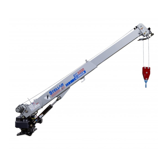
Telescopic crane
Hide thumbs
Also See for EC3200:
- Owner's manual (30 pages) ,
- Owner's manual (47 pages) ,
- Owner's manual (48 pages)
Table of Contents
Advertisement
O
WNER
Safety, Installation, Maintenance, and Operation
Subject to Change without Notification.
© 2008 Stellar Industries, Inc.
'
S
EC3200 Telescopic Crane
Angle
Angle
Indicator
Indicator
0 0
Stellar Industries, Inc.
190 State Street
PO Box 169
Garner, IA 50438
800-321-3741
Fax: 641-923-2811
www.stellarindustries.com
M
ANUAL
EC3200
EC
3200
42818
42818
Manual Part No. 44024
Last Revision: 10/09/08
Advertisement
Table of Contents
Troubleshooting

Subscribe to Our Youtube Channel
Related Manuals for stellar labs EC3200


Summary of Contents for stellar labs EC3200
- Page 1 ’ WNER ANUAL Safety, Installation, Maintenance, and Operation EC3200 Telescopic Crane EC3200 3200 Angle Angle Indicator Indicator 42818 42818 Stellar Industries, Inc. 190 State Street PO Box 169 Garner, IA 50438 800-321-3741 Fax: 641-923-2811 www.stellarindustries.com Subject to Change without Notification.
- Page 2 EC3200 Manual Revisions Date of Revision Section Revised Description of Revision August 5th, 2008 Chapter 6: Updated Mast Assembly drawing and Control Kit Installation drawing per engineering changes. Chapter 7: Assembly...
-
Page 3: Table Of Contents
Control Kit - PN 42804 ........32 EC3200 Wiring Diagram ....... . . 33 Valve Bank Drawing . -
Page 4: Introduction
EC3200 Owner’s Manual - PN 44024 Introduction Stellar Cranes are designed to provide safe Stellar manufactured cranes in general and and dependable service for a variety of may or may not apply to your specific operations. With proper use and model. -
Page 5: Chapter 1 - Safety
Safety Chapter 1 - Safety Please Read the Following Carefully! This Do not wear rings, wristwatch, jewelry, loose- portion of the manual contains information fitting or hanging clothing such as ties, torn regarding all Stellar manufactured cranes. garments, scarves, unbuttoned jackets or Some items contained within this chapter unzipped overalls, which could get caught up may not apply to your specific equipment. - Page 6 EC3200 Owner’s Manual - PN 44024 STABILITY Do not walk under suspended loads. Know the crane components and their capabilities and limitations. Overloading the Do not position any load over a person nor crane may result in serious injury to self and...
-
Page 7: Chapter 2 - Operation
Operation Chapter 2 - Operation Crane Controls This chapter contains information regarding the operation of Stellar manufactured 1. Be familiar with the sequence and telescopic cranes. Please study the operation of the crane controls. following pages to ensure your familiarity with the operation process. -
Page 8: Function Hetronic Remote
EC3200 Owner’s Manual - PN 44024 5 Function Hetronic Remote 1. Engage the PTO (If applicable) 3. Position Outriggers A. Engage the parking brake. Once the PTO is engaged, extend the outriggers B. Place the transmission using the control levers or switches marked in the Neutral position. -
Page 9: Manual Operation
Operation Manual Operation Crane Precautions 1. Movement of the control levers should be If the remote control malfunctions, follow slow and smooth to meter oil flow for safe these steps to operate the crane manually: operation. Avoid jerky and sudden movements. -
Page 10: Operator Information
EC3200 Owner’s Manual - PN 44024 Operator Information OPERATOR REQUIREMENTS OPERATOR CONDUCT 1. Operation is limited to the following 1. Operators will not engage in any people: operation that would cause them to divert A. Designated individual. attention away from the operation of the B. -
Page 11: Chapter 3 - Maintenance
Maintenance Chapter 3 - Maintenance Daily Inspection WARNING - Read the Following before Daily Inspection should occur each day performing any maintenance on the before the crane is put into use. Each day, crane. inspect the crane for all of the following: 1. - Page 12 EC3200 Owner’s Manual - PN 44024 Weekly Inspection Service Weekly Inspection should occur at the The following general suggestions should beginning of every work week. Each week, be helpful in analyzing and servicing your inspect the crane for all of the following: crane.
-
Page 13: Lubrication Recommendations
Maintenance Lubrication Recommendations Component Location Recommendation Engine Crankcase Apply Manufacturer’s Recommendations Hydraulic System Reservoir Below –5*F Petro-Canada Arctic MV 15 (ISO 22) -5*F to 90*F Petro-Canada HYDREX 32 (ISO 32) Above 90*F Petro-Canada HYDREX 46 (ISO 46) Open Gears Hand Precision XL3 Moly EP 2 (NLGI 2 grease with moly) Bearings, grease... -
Page 14: Wire Rope Maintenance
EC3200 Owner’s Manual - PN 44024 Wire Rope Maintenance surface wires of the rope need to be inspected. This inspection will be concerned with discovering damage Wire Rope Inspection Points that may be an immediate hazard. The While inspection of the entire rope is... -
Page 15: Torque Data Chart
Maintenance Holding Valve Inspection Procedure Torque Data Chart The cylinders are equipped with holding valves that prevent sudden movement of the cylinder rods in the event of a hydraulic hose or hydraulic component failure. The Grade 5 Grade 8 Grade 9 valve is checked in the following manner: 1. -
Page 16: Inspection Checklist
EC3200 Owner’s Manual - PN 44024 Inspection Checklist Type of Inspection (check one) Use of this checklist is subject to terms of the Daily Quarterly Stellar Warranty information. Additional copies of (if deficiency found) this checklist can be obtained by contacting... -
Page 17: Daily Inspection
Maintenance Daily Inspection Frequency Inspection Description Status Decals All load charts, safety & warning Decals, & control Decals are present and legible. Check all safety devices for proper operation. Controls Control mechanisms for proper operation of all functions, leaks, & cracks. Station Control mechanisms for proper operation of all functions, leaks, &... -
Page 18: Monthly Inspection
EC3200 Owner’s Manual - PN 44024 Monthly Inspection Frequency Inspection Description Status Daily All Daily Inspections. Cylinders Visual inspection of cylinders for leakage at rod, fittings, & welds. Damage to rod & case. Valves Holding valves for proper operation. Valves Control valve for leaks at fittings &... -
Page 19: Quarterly Inspection
Maintenance Quarterly Inspection Frequency Inspection Description Status Daily All daily inspections. Monthly All monthly inspections. Rotation Sys Rotation bearing for proper torque of all mounting bolts. Hardware Base mounting bolts for proper torque. Structure All structural members for deformation, cracks, & corrosion. Base Outrigger beams &... - Page 20 EC3200 Owner’s Manual - PN 44024 Quarterly Inspection Continued... Frequency Inspection Description Status Hyd Lines Hoses, fittings, & tubing for proper routing, leakage, blistering, deformation, & excessive abrasion. Pressure line(s) from pump to control valve Return line(s) from control valve to reservoir...
-
Page 21: Annual Inspection
Maintenance Annual Inspection Frequency Inspection Description Status Daily All daily inspection items. Monthly All monthly inspection items. Quarterly All quarterly inspection items. Hyd System Hydraulic fluid change per maintenance schedule. Controls Control valve calibration for correct pressures & relief valve settings. Valves Safety valve calibration for correct pressures &... -
Page 22: Inspection Notes
EC3200 Owner’s Manual - PN 44024 Inspection Notes... -
Page 23: Chapter 4 - Specifications
Specifications Chapter 4 - Specifications Model EC3200 Crane SPECIFICATION SHEET Crane Rating: 11,500 ft-lbs (1.59 ton-meters) Standard Boom Length: 7’ (2.13 m) from CL of Crane Boom Extension: 1st stage: Hydraulic 48" (121.9 cm) 2nd stage: Manual 48" (121.9 cm) Maximum Horizontal Reach: 15’... -
Page 24: Capacity Chart - Decal Pn 42817
EC3200 Owner’s Manual - PN 44024 Capacity Chart - Decal PN 42817 Reach in Feet/Meters *3200 lbs *3025 lbs Capacity in Pounds/Kilograms 16’2” 1450 kg 1372 kg 4.92 *1550 lbs 15’ 703 KG 4.57 3200 lbs 3200 lbs 1090 lbs... -
Page 25: Chapter 5 - Decals
Decals Chapter 5 - Decals Decals of Note NOTE - Not all decals are featured in this chapter. Please refer to the decal placement drawing at the end of this chapter for a complete list of decals and their respective placement on the crane and service body. - Page 26 EC3200 Owner’s Manual - PN 44024 Instructional Decal Location: At Stow Hook area Function: To caution the operator not to use the stow hook for any lifting applications. PN: 24712 Foot Crushing Hazard Decal Location: On each outrigger leg. Function: To inform the operator and...
- Page 27 Decals Free Falling Manual Boom Decal Electrocution Hazard Decal Location: Inside Crane Compartment, on Location: Inside Crane Compartment, on Compartment Door Compartment Door Function: To inform the operator of the hazard Function: To inform the operator of the hazard associated with free falling manual boom associated with overloading the crane, the extensions, the possible consequences should possible consequences should the hazard...
- Page 28 EC3200 Owner’s Manual - PN 44024 Operation Hazard Decal Moving Boom Hazard Decal Location:Inside Crane Compartment, on Location:Inside Crane Compartment, on Compartment Door Compartment Door Function: To inform the operator of the need Function: To inform the operator and other...
-
Page 29: Decal Kit Placement - Pn 42816
42818 PN 42816 *USE THESE DECALS WITH BODY PACKAGE 18472 DECAL MANUAL OPERATION 13819 DECAL-ANGLE INDICATOR SS 42820 DECAL VB CONTROL EC3200 13820 DECAL ANGLE INDICATOR CS 35234 DECAL STELLAR MADE IN THE USA C1179 DECAL-ELECTROCUTION 4.5x7.5 42819 DECAL SNATCH BLOCK CAP 3 TON C5918 DECAL-DANGER MOVING O.R. - Page 30 EC3200 Owner’s Manual - PN 44024...
-
Page 31: Chapter 6 - Installation
According to Federal Law (49 cfr part 571), general guide for the installation of a Stellar each final-stage manufacturer shall EC3200 Telescopic Crane on a Stellar complete the vehicle in such a manner that Service Body. Each installation is considered... -
Page 32: Installation Overview
Installation Overview 1. Determine that the mounting location for the EC3200 crane is at least 18” x 15” (45.7 x 38.1 cm). 2. Use the detail on the following page to drill .938” diameter holes into the mounting plate. Run tap on the threads of the base to be sure they are clean. -
Page 33: Ec3200 Mounting Detail
Installation EC3200 Mounting Detail Standard Narrow Base FRONT FRONT ÿ 3.00 14.75 10.00 5.00 7.38 7.38 5.00 14.75 10.00 Flatbed Body Reinforcement Hole Mounting Detail If it has been determined that the destination body won’t support the crane with a fully rated load, the body must be reinforced. -
Page 34: Ec3200 Installation Drawing
EC3200 Owner’s Manual - PN 44024 EC3200 Installation Drawing ITEM PART DESCRIPTION 8648 WASHER 0.88 SAE FLAT YELLOW GR8 42985 CAP SCR 0.88-9X 1.75 HHGR8ZY... -
Page 35: Hydraulic Kit - Pn 42799
Installation Hydraulic Kit - PN 42799 12 10 ROTATION CCW BOOM DOWN EXTENSION RETRACT ROTATION BOOM UP ROTATION CW EXTENSION EXTEND MAIN PN 42799 3861 FTG ML FM O'RING 90 DEG SWITCH PRES OVERLD 744.6-S03R-2900N 3862 FTG ADAPT 4-6 F5OLO-S C4922 D1291 FTG ADAPT 4-F5OLO-S... -
Page 36: Control Kit - Pn 42804
EC3200 Owner’s Manual - PN 44024 Control Kit - PN 42804 PN 42804... -
Page 37: Ec3200 Wiring Diagram
Installation EC3200 Wiring Diagram FUSE 250 AMP ISO/SWITCH 250 AMP (STELLAR SUPPLIED) TRUCK BATTERY UNDERHOOD SWITCH BATTERY CHARGE CRANE CRANE HARNESS START MOTOR SOLENOID GROUND GROUND POST TRUCK BATTERY GROUND CRANE COMPARTMENT SWITCH POWER 10 AMP NOTE: CAB OR CRANE... -
Page 38: Valve Bank Drawing
EC3200 Owner’s Manual - PN 44024 Valve Bank Drawing INNER INNER DOWN... -
Page 39: Stability Procedure
2. Set outriggers so that they make contact with firm, level footings. 3. Operate the crane under partial load to assure operator proficiency and proper machine function. EC3200 Stability Data Max Horizontal Reach: 180” (From the center of rotation to boom tip) Stability Test Weight: 875 lbs. -
Page 40: Stability Capacity Chart
EC3200 Owner’s Manual - PN 44024 Stability Capacity Chart STABILITY CAPACITY CHART For a decal version of this capacity chart, please contact Stellar Customer Service at (800) 321-3741... -
Page 41: Chapter 7 - Assembly Drawings
Assembly Drawings Chapter 7 - Assembly Drawings Base Assembly - PN 42525 PN 42525 41640 BEARING SWING DRIVE 170-00058-1 42840 ROTATION MOTOR EC3200 21151 GASKET MOTOR 008-10056-1 1 ref D1307 CAP SCR 0.50-13X1.25 SH 30750 CAP SCR 0.50-13X3.50 HHGR8 D1345 FTG CPRSN 0.12NPT/0.25 TUBE... -
Page 42: Base Assembly (Narrow Version) - Pn 44613
EC3200 Owner’s Manual - PN 44024 Base Assembly (Narrow Version) - PN 44613 PN 44613 41640 BEARING SWING DRIVE 170-00058-1 42840 ROTATION MOTOR EC3200 21151 GASKET MOTOR 008-10056-1 1 ref D1307 CAP SCR 0.50-13X1.25 SH 30750 CAP SCR 0.50-13X3.50 HHGR8 D1345 FTG CPRSN 0.12NPT/0.25 TUBE... -
Page 43: Mast Assembly - Pn 42787
0345 CAP SCR 0.38-16X1.50 HHGR5 0479 CAP SCR 0.25-20X0.75 HHGR5 0478 CAP SCR 0.25-20X0.50 HHGR5 43579 CAP SCR 0.44-14X2.75 MOD EC3200 47411 BRKT OVERRIDE BUTTON EC3200 0343 WASHER 0.31 USS FLAT ZINC 0420 CAP SCR 0.31-18X0.75 HHGR5 NOTE: WINCH CONTROLLER(P/N 42821) -
Page 44: Main Boom Assembly - Pn 42512
EC3200 Owner’s Manual - PN 44024 Main Boom Assembly - PN 42512 MOUNTING HARDWARE WILL BE PART OF THE WINCH PACKAGE. USE ALL HARDWARE, EXCEPT BOLTS. PN 42512 ITEM PART DESCRIPTION QTY. 42303 INNER BOOM EC3200 41641 WINCH DC2000 WARN 63899... -
Page 45: Extension Boom Assembly - Pn 42520
WASHER 0.50 FLAT GR8 10172 CAP SCR 0.50-13X1.00 HHGR8 ZY 42509 WEAR PAD 0.38X1.38X1.50 42312 EXT BOOM 2ND EC3200 42978PC FLAT BOOM STOP EC3200 42317 SHEAVE EC3200 5.00 DIA .22R/1.00THK 0423 MACHY WASHER 0.75ID 10GA 0507 CAP SCR 0.50-13X4.50 HHGR5... -
Page 46: Cable & Hook Assembly - Pn 42781
EC3200 Owner’s Manual - PN 44024 Cable & Hook Assembly - PN 42781 PN 42781 42523PC PLATE SNATCH BLOCK EC3200 42317 SHEAVE EC3200 5.00 DIA .22R/1.00THK 0352 WASHER 0.50 USS FLAT ZINC 5468 NUT 0.50-13 HHGR8 NYLOC 27810 SPACER 3315 SNATCH BLOCK UHMW... -
Page 47: Chapter 8 - Replacement Parts
PART# DESCRIPTION 42840 HYDRAULIC SWING MOTOR 21151 GASKET - HYDRAULIC SWING MOTOR 42513 POWER UNIT 12V EC3200 44028 VALVE CARTRIDGE - POWER UNIT 12V #19012-D 44027 VALVE COIL - POWER UNIT 12V #11494-D 44029 MOTOR 12V - POWER UNIT #08111-1... - Page 48 EC3200 Owner’s Manual - PN 44024...
-
Page 49: Chapter 9 - Troubleshooting
Troubleshooting Chapter 9 - Troubleshooting This chapter will list a number of potential problems that may occur while operating the crane. Most problems are easily solved using the solutions portion of this chapter. If problems persist, please contact Customer Service at Stellar Industries 1-800-321-3741. Problem: Crane will not operate. - Page 50 EC3200 Owner’s Manual - PN 44024 Problem: Cylinder drifts outward or Problem: Winch “Up”, and Main Cylinder downward. “Down”, are the only functions that don’t Solutions: operate. Solutions: • Check to see if there is air in the hydraulic system. Operate all cylinders •...
-
Page 51: Hoist Troubleshooting
Troubleshooting Hoist Troubleshooting For detailed information on the crane hoist, please refer to the WARN Industrial Hoists Installation and Operator’s Guide (WARN PN 72561 A1). PROBLEM PROBABLE CAUSE CORRECTION Hoist won’t operate in Power is not connected.. Check wiring connections. Check for 12v at either direction or motor positive terminal on controller. -
Page 52: Function Hetronic Radio Remote Troubleshooting
EC3200 Owner’s Manual - PN 44024 5 Function Hetronic Radio Remote Troubleshooting If the system does not operate after normal start-up, follow the recommended troubleshooting sequence to help isolate the cause and determine corrective action. Transmitter Receiver • Is the E-Stop push button pulled out? •... -
Page 53: Receiver Troubleshooting
Troubleshooting Transmitter Troubleshooting Notice: When testing the transmitter, the receiver may become active resulting in system operation. Always assume the system is working and will respond when testing a transmitter. Status LED Troubleshooting LED Indication Possible Cause LED is off Transmitter is off LED flashes Transmitter is operating in a normal mode... -
Page 54: Warranty Information
Limited Warranty Statement Stellar Industries, Inc. (Stellar) warrants products designed and manufactured by Stellar to be free from defects in material and workmanship under proper use and maintenance. Products must be installed and operated in accordance with Stellar’s written instructions and capacities. The warranty period shall cover the following: Twelve (12) month warranty on parts from the date recorded by Stellar as the in-service date, not to extend beyond twenty-four (24) months from date of manufacture,...
Need help?
Do you have a question about the EC3200 and is the answer not in the manual?
Questions and answers