
Related Manuals for meitav-tec MTSC/SUPER/HU


Summary of Contents for meitav-tec MTSC/SUPER/HU
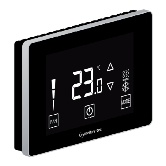
- Page 1 Touch Screen Thermostat MTSC/SUPER/HU Owner’s manual and technician settings Rev 2.1...
- Page 2 - 2 -...
-
Page 3: Table Of Contents
Index 1. Owner’s Manual ………………………………………………..4 1.1 Quick Guide……………………………………………………. 4 1.2 Turning the unit ON or OFF………………………………….. 5 1.3 Adjusting the set-point temperature ………………………... 5 1.4 Switch between temperature scales ……………………….. 5 1.5 Switching between System modes………………………….. 6 1.6 Switching between Fan speeds …………………………….. 6 1.7 Fan on demand (Auto fan)….……………………………….. -
Page 4: Owner's Manual
1. Owner’s manual 1.1 Quick Guide System ON % Humidity Ambient / display Set-point temperature Set-point display adjustment Fan speeds Modes indication indication Press to switch between Press to switch between Press to fan speeds: system modes: turn system ON or OFF *Auto High Med. -
Page 5: Turning The Unit On Or Off
1.2 Turning the unit ON or OFF Press the button to turn the unit ON – system mode and fan speed symbols will appear on display. Press again to turn the unit OFF – the symbols will disappear. Unit OFF Unit ON 1.3 Adjusting the set-point temperature While the thermostat is ON, press the... -
Page 6: Switching Between System Modes
1.5 Switching between system modes Press the button to switch between system modes: Cool Heat Auto mode only Notes: - During demand for cooling (cooling active), the will flash. - During demand for heating (heating active), the will flash. The selection of system modes may be disabled depending on system configuration. -
Page 7: Fan On Demand (Auto Fan)
1.7 Fan on demand (Auto fan) Press and hold the button to activate or deactivate fan on demand (Auto fan) function. Notes: - When activated, the fan will run with demand for cooling or heating (When activated in floor heating configuration - the fan will not run together with the floor heating output. -
Page 8: Installation Instructions
2. Installation Instructions The MTC/SUPER/HU Thermostat designed for flush mounting in the room to be controlled. It should be located where the occupant can easily read the display and use the controls. If the built in temperature and humidity sensors are being used to measure room temperature and humidity, the panel should be placed where the temperature is representative of the general room conditions, away from cold or warm air draughts, radiant heat and... - Page 9 2. Installation Instructions (cont’) Installation procedure: 1. separate the front display from the back plastic cover by inserting a a small flat screwdriver into each of the three slots as shown in the picture and rotating it gently. 2. Remove the front display and keep it in a safe place. 3.
- Page 10 2. Installation Instructions (cont’) - 10 -...
-
Page 11: Wiring Configuration And Dip Switches
3. Wiring configuration and DIP Switches *External sensor / Soft start in heat sensor / Deicing in cool sensor / Door switch (options) T2 change over sensor / Soft ****See options start in heat sensor / Remote on next pages OFF switch / Remote economy switch / External PIR See options on... - Page 12 3. Wiring configuration and DIP Switches – AC systems HC32-1S HC32-1S HP42-1S HP42-1S (HU only) (HU + DeHU) (HU only) (HU + DeHU) Heat element 3 Heat element 3 Heat element 2 Heat element 2 Heat element 2 Heat element 2 Heat element 1 Heat element 1 Fan (1 speed)
- Page 13 3. Wiring configuration and DIP Switches – AC systems HP22-3S HP22-3S HP21-3S HP21-3S (HU only) (HU + DeHU) (HU only) (HU + DeHU) Fan high Fan high Fan high Fan high Fan medium Fan medium Fan medium Fan medium Fan low Fan low Fan low Fan low...
- Page 14 3. Wiring configuration and DIP Switches – AC systems HC21-3S HC21-3S HP22-VFS (3S) HP21-VFS (3S) (HU only) (HU + DeHU) (HU only) (HU only) Fan high Fan high Fan high Fan high Fan medium Fan medium Fan medium Fan medium Fan low Fan low Fan low...
- Page 15 3. Wiring configuration and DIP Switches – AC / Fan coil systems HC21-VFS (3S) (HU only) Fan high Fan medium Fan low Heat element 2 Compressor 1 Heat element 1 (see SW1.4 HC) Humidifier 0V OFF / 10V ON Fan VFS SW1.8 =Protocol: ON –...
- Page 16 3. Wiring configuration and DIP Switches – AC / Fan coil systems 2-Pipe 3S 2-Pipe 3S 2-Pipe VFS (3S) 4-Pipe 3S (HU only) (HU + DeHU) (HU only) (HU only) Fan high Fan high Fan high Fan high Fan medium Fan medium Fan medium Fan medium...
- Page 17 3. Wiring configuration and DIP Switches – Fan coil systems 4-Pipe 3S 4-Pipe VFS (3S) 4-Pipe 3S 4-Pipe VFS (3S) (HU + DeHU) (HU only) (HU + DeHU) F.H (HU only) F.H Fan high Fan high Fan high** Fan high** Fan medium Fan medium Fan medium**...
-
Page 18: Technician Settings
4. Technician Settings Enter technician settings Adjust the set-point temperature to 10ºC. To enter technician settings, press and hold the button for 5 seconds. Use the button to advance to the next parameter. Use the button to return to return to the previous parameter. Press the button or wait 60 seconds to exit technician settings and return to normal display. - Page 19 4. Technician settings (cont’) P1 – Offset for temperature readings calibration Range: -6…+6°C / -9…+9°F. Default: 0°C / 0°F. P2 – Set point limit for cooling Range: 5…35°C / 41…90°F. Default: 5°C / 35°F. P3 – Set point limit for heating Range: 5…35°C / 41…95°F.
- Page 20 4. Technician settings (cont’) P7 – Lock the [+] and [-] buttons (Set buttons) “01” - [+] and [-] buttons Locked “00” - [+] and [-] buttons unlocked (default) P8 – Functionality of T1 terminals “00” - T1 terminals are not in use (default) “01”...
- Page 21 4. Technician settings (cont’) P11 – Window contact delay time Range: 0…999 seconds Default: 600 seconds P12 – Door switch / Door key-tag (terminals T1,0) polarity “00” - Normally open (default) “01” - Normally close P13 – Door switch / Door key-tag delay time Range: 0…999 seconds Default:...
- Page 22 4. Technician settings (cont’) P17 – PIR (occupancy sensor) delay time before switching to unoccupied mode (ON delay) Range: 0…250 minutes, Default: 20 minutes P19 – PIR (Occupancy sensor) polarity “00” - Normally open (default) “01” - Normally close P25 – Economy set point for cooling Range: 5…35°C / 41…90°F Default:...
- Page 23 4. Technician settings (cont’) P27 – Time on-delay between heating stages Range: 0…600 seconds Default: 5 seconds P28 – Time off-delay between heating stages Range: 0…600 seconds Default: 1 seconds P30 – Beeper ON or OFF “01” - Beeper ON (default) “00”...
- Page 24 4. Technician settings (cont’) P35 – Enable/Disable Freeze protection “01” - Enable freeze protection (default) “00” - Disable freeze protection P36 – Freeze protection cut-in set point Range: 8...15°C / 46…59°F Default: 8°C / 46°F P37 – Freeze protection cut-out set point Range: 10...17°C / 50…63°F Default: 10°C / 50°F P40 –...
- Page 25 4. Technician settings (cont’) P43 – Soft start in heat – cut-in temperature The fan will not start before the temperature on T3 sensor reaches the cut-in temperature. Range: 14...37°C / 57…99°F Default: 36°C / 96°F P44 – Soft start in heat – cut-out temperature The fan will stop if the temperature on T3 sensor drops below the cut-out temperature.
- Page 26 4. Technician settings (cont’) P49 – Shift between Cool and Heat in Auto change over mode Range: 0...10°C / 0…20°F Default: 2°C / 4°F P51 – Shift between Heating stages Range: 0...10°C / 0…20°F Default: 2°C / 4°F P52 – Cool proportional band (FC only!) Range: 2...10°C / 4…20°F Default: 2°C / 4°F P53 –...
- Page 27 4. Technician settings (cont’) P55 – Heat proportional band (FC only!) Range: 2...10°C / 4…20°F Default: 2°C / 4°F P56 – Heat proportional low limit (FC only!) Range: 0...100% Default: 0% P57 – Heat proportional high limit (FC only!) Range: 0...100% Default: 100% P60 –...
- Page 28 4. Technician settings (cont’) P63 – Time on-delay between cooling stages Range: 0…600 seconds Default: 5 seconds P64 – Time off-delay between cooling stages Range: 0…600 seconds Default: 1 seconds P65 – Fan VFS proportional band in cooling Range: 2...10°C / 4…20°F Default: 2°C / 4°F P66 –...
- Page 29 4. Technician settings (cont’) P70 – Fan VFS Low speed percent in heating Range: 0...30% Default: 30% P71 – Fan VFS Medium speed percent in heating Range: 30...60% Default: 50% P72 – Fan VFS High speed percent in heating Range: 60...100% Default: 80% P73 –...
- Page 30 4. Technician settings (cont’) P76 – Fan VFS Low limit in cooling Range: 0...100% Default: 0% P77 – Fan VFS High limit in cooling Range: 0...100% Default: 100% P78 – Fan VFS Low limit in heating Range: 0...100% Default: 0% P79 –...
- Page 31 4. Technician settings (cont’) P85 – Deice in cool – cut-in temperature (AC only!) Range: -20...99°C Default: 0°C P86 – Deice in cool – cut-out temperature (AC only!) Range: -20...99°C Default: 8°C P87 – Deice in heat time (AC only!) Range: 120...420 Seconds Default: 300 Seconds P88 –...
- Page 32 4. Technician settings (cont’) P99 – One or Two set points (for cool and for heat) “00” - One set point for cooling and heating (default) “01” - two set points – one for cool and one for heat P100 – Enable/Disable Screen dimming “00”...
- Page 33 4. Technician settings (cont’) P189 – Dehumidification cycle in unoccupied mode Range: 0...600 minutes Default: 20 minutes P190 – Dehumidification break time in unoccupied mode Range: 0...900 minutes Default: 40 minutes P191 – Door switch/key-tag function for unoccupied mode 0 – Turn unit off 1 –...
- Page 34 4. Technician settings (cont’) P196 – Dead zone between humidification and dehumidification Range: 0...100 %RH Default: 0 %RH P197 – Humidity set-point Range: 20...100 %RH Default: 80 %RH P200 – Restore defaults Press the button to restore defaults Press the button twice to return to normal display Press the button to return to parameter P1 or wait 60...
-
Page 35: Mac Address
5. MAC Address Enter MAC Address settings Adjust the set-point temperature to 11ºC – the button will appear on display. To enter MAC Address settings, press and hold the button for 5 seconds. Use the buttons to change the MAC Address. Set “0”... - Page 36 www.meitavtec.com...
Need help?
Do you have a question about the MTSC/SUPER/HU and is the answer not in the manual?
Questions and answers