
Subscribe to Our Youtube Channel
Related Manuals for meitav-tec ETNC-SUPER-PROG-HU-PIR


Summary of Contents for meitav-tec ETNC-SUPER-PROG-HU-PIR
- Page 1 Prog On/Off Mode Fan ETNC-SUPER-PROG-HU-PIR Owner’s manual & Technician Settings Rev.1.5.a...
- Page 2 Index Operating instructions……………………………………..…………………………………….………….4-7 Quick guide……………………………………………………………………………………………… 4 Turning the thermostat ON and OFF ………………………………………………………………… 5 Selecting temperature scale ………………………………………………………………………… 5 Adjusting the Set point temperature (for 1 set point and 2 set points configurations) ………….. 5 Selecting system mode………………………………………………………………………………… 6 Selecting Fan speeds (for 2 and 3 fan speeds configuration) …………………………………….. 6 Turning Auto fan ON or OFF (fan on demand)………………………………………………………...
- Page 3 Index Technician settings……………………………………………...…………………………….………….. 35-59 P37 – Freeze protection cut-out set point P86 – Deice in cool – cut-out temperature P40 – View filter counter (hours) – Read only P87 – Deice in heat time P41 – Reset filter time P88 – Deice in heat break time P42 –...
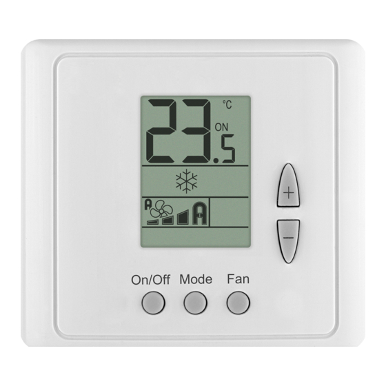
- Page 4 Operating instructions Quick guide Temperature/Humidity Fan speeds indication: indications: Auto speed Temperature scale High Ambient Humidity Medium Set-point adjust. Fan on demand Ambient/Set-point indication temperature Ambient Indications: humidity indication Alarm Thermostat On/Off indication Button locked Program active System MODE indication: Program events indications: Fan only Cooling...
- Page 5 Operating instructions Turning the thermostat ON and OFF Press the [On/Off] button to turn the thermostat ON or OFF. Selecting temperature scale Press the [C/F] button to switch between temperature scales. Celsius Fahrenheit Adjusting the Set point temperature In One set point configuration: Press the [+] or [-] buttons once to view the set point temperature.
- Page 6 Operating instructions (Cont’) Selecting system mode Press the [Mode] button to switch between system modes. Notes: 1. During demand for cooling or heating, the active mode will flash. Cool Heat 2. In Auto mode, the active mode icon (Cool or Heat) will flash. 3.
- Page 7 Operating instructions (Cont’) Economy mode Economy mode can be activated by Economy by: triggering a Window contact - Remote - Window contact - Remote on/off switch - Window contact - Remote economy switch on/off switch Window contact - remote economy switch, door switch, key-tag, the built-in/external PIR sensor Economy by: - Built-in/External PIR...
- Page 8 Economizer Economizer is used to reduce the energy consumed by the cooling systems, by using low external air temperatures to assist in the chilling process. When outdoor temperatures are lower relative to indoor (room) temperatures, the system utilizes the cool outdoor air as a free cooling source. The outdoor temperature (Teconomizer) triggering the activation of the economizer, can be measured by the temperature sensor connected to T1,0 terminals (technician parameter P08="05") or by setting a temperature value manually through communication - AV#129 "TEconomizerEffective".
-
Page 9: Weekly Program
Weekly program A. General Prior to programming, make sure that parameters P107, P108 and P109 in the technician settings are configured correctly. Program types The thermostat can be configured to run four different types of weekly programs (set by technician parameter P107): 1. - Page 10 Weekly program (Cont’) Programming procedure The detailed programming procedure is described in the next sections. Make sure to follow the right programming procedure, suitable for the program type and features selected by technician settings. Press the [C/F-Prog] button to enter and proceed through the steps of the real time clock and programming procedure.
- Page 11 Weekly program (Cont’) Adjusting “EU type” daily programs – Start time / Stop time Start time Press the [C/F – Prog] button – the programmed weekday(s), “Prog 1” indicating the first program event of the day and the word “Start” will appear on display. The HOURS will flash Note: If this is the first time a program is being set, the symbols “--“...
- Page 12 Weekly program (Cont’) Adjusting “US type” daily programs – Start time / Mode / Fan speed / Set points Start time Press the [C/F – Prog] button – the programmed weekday(s), “Prog 1” indicating the first program event of the day and the word “Start” will appear on display. The HOURS will flash Note: If this is the first time a program is being set, the symbols “--“...
- Page 13 Weekly program (Cont’) Set point Press the [C/F – Prog] button again – the set point will flash. Note: If the thermostat is configured to have two set points, first adjusts the set point for cooling and then the set point for heating. Use the [+] and [-] buttons to select the set point of the first event Follow the steps above for the other schedule events of the same day (Prog 2 for 2 event per day, or Prog 2, 3 and 4 for four events per day).
-
Page 14: Installation
Installation The ETNC-SUPER-PROG-HU-PIR is designed for wall mounting in the room to be controlled. It should be located where the occupant can easily read the LCD display and use the controls and where the built in PIR occupancy sensor can easily detect any movement in the room (consider PIR detection are below). -
Page 15: Pir Detection Area
Wiring *External sensor / Soft start in heat sensor / Deicing in cool sensor / Door switch T2 change over sensor / Soft For outputs 11-16 – start in heat sensor / Window Please refer to wiring and contact Remote On/Off DIP switches configurations switch / Window contact for different outputs options... - Page 16 DIP Switch and Jumpers configuration JP2JP3 JP2, JP3 – Not in use SW4.1 – Without valves in FC config. SW4.4 – End of line resistor (120Ω) OFF - Enable valves control OFF (Open) - Not End of line ON - Disable valves control ON (Close) - End of line...
- Page 17 AC Configurations index AC Configurations without humidification/dehumidification Outputs Configuration: Heat elements Compressors Heat pump Fan VFS Fan speeds Economizer Humidifier Dehumidifier Reheat (Dehumidify) AC Configurations with humidification/dehumidification Outputs Configuration: Heat elements Compressors Heat pump Fan VFS Fan speeds Economizer Humidifier Dehumidifier Reheat (Dehumidify) Option...
-
Page 18: Fc Configurations For 2-Pipe Systems
FC Configurations for 2-Pipe systems FC Configurations for 2-Pipe systems without humidification/dehumidification Outputs Configuration: Cl/Ht valve / Cl/Ht valve PID Heat element (2 stage) Fan VFS Fan speeds Economizer Humidifier Dehumidifier Reheat (Dehumidify) FC Configurations for 2-Pipe systems with humidification/dehumidification Outputs Configuration: Cool/Heat valve... -
Page 19: Fc Configurations For 4-Pipe Systems / Floor Heating
FC Configurations for 4-Pipe systems / Floor heating FC Configurations for 4-Pipe systems without humidification/dehumidification Outputs Configuration: Cool valve / Cool valve PID Heat valve / Heat valve PID Heat element (2 stage) Fan VFS Fan speeds Economizer Humidifier Dehumidifier Reheat (Dehumidify) Floor heating FC Configurations for 4-Pipe systems with humidification/dehumidification... - Page 20 Wiring and DIP Switches – AC systems HC32 HP42 HP22 HP21 1 Speed fan 1 Speed fan 2/3 Speeds fan 2/3 Speeds fan Heat element 3 Heat element 2 Fan high Fan high stage heat) stage heat) Fan medium Fan medium Heat element 2 Heat element 1 (or Economizer...
- Page 21 Wiring and DIP Switches – AC systems HC21 HP11 HC11 2/3 Speeds fan Fan VFS Fan VFS Fan high Fan medium Economizer Economizer (or Economizer (option – SW1.6 ON) (option – SW1.6 ON) Fan low Heat element 2 Heat pump Heat element stage heat) Compressor...
- Page 22 Wiring and DIP Switches – AC systems HC22 HP32 1 Speed fan, 1 Speed fan, Economizer Economizer Heat element 2 Heat element stage heat) stage heat) Economizer Economizer (option – SW1.6 ON) (option – SW1.6 ON) Fan (1 speed) Fan (1 speed) Compressor 2 Compressor 2 Compressor 1...
- Page 23 Wiring and DIP Switches – AC systems w/wo Humidifier for humidification, with Reheat for dehumidification HC22 HP31 HC11 HP21 1 Speed fan, 1 Speed fan, 2/3 Speeds fan, 2/3 Speeds fan, Humidifier, Humidifier, Humidifier, Reheat for Reheat for Reheat for Reheat for Dehumidification Dehumidification...
- Page 24 Wiring and DIP Switches – AC systems with Humidifier for humidification HP21 HC12 1 Speed fan, 1 Speed fan, Humidifier, Reheat for Humidifier Dehumidification Heat element Heat element stage heat) Economizer Economizer (option – SW1.6 ON) (option – SW1.6 ON) Fan (1 speed) Fan (1 speed) Compressor 2...
- Page 25 Wiring and DIP Switches – AC systems with humidifier and Dehumidifier HC21 HC11 HP11 HP21 1 Speed fan, 1 Speed fan, 1 Speed fan, 1 Speed fan, Humidifier, Humidifier, Humidifier, Humidifier, Dehumidifier Dehumidifier Dehumidifier Dehumidifier Heat element 2 Heat element Heat pump Heat pump stage heat)
- Page 26 Wiring and DIP Switches – FC systems – 2-Pipe 2-Pipe, 2-Pipe, 2-Pipe, 2-Pipe, 1/2/3 Speeds fan Fan VFS, 1/2/3 Speeds fan Fan VFS Cool/Heat PID Cool/Heat PID Fan high Fan high Fan medium Fan medium Economizer Economizer (or Economizer (or Economizer (option –...
- Page 27 Wiring and DIP Switches – FC systems – 2-Pipe with Humidifier for humidification and Reheat for dehumidification 2-Pipe, 2-Pipe, 2-Pipe, 2-Pipe, 1/2/3 Speeds fan 1/2/3 Speeds fan Fan VFS, Fan VFS, Cool/Heat PID, Humidifier, Cool/Heat PID, Reheat for Humidifier, Reheat for Reheat for Dehumidification Reheat for...
- Page 28 Wiring and DIP Switches – FC systems – 2-Pipe with Dehumidifier, w/wo Humidifier 2-Pipe, 2-Pipe, 2-Pipe, 1/2/3 Speeds fan 1/2/3 Speeds fan Fan VFS, Humidifier, Cool/Heat PID, Dehumidifier Dehumidifier Dehumidifier Fan high Fan high Fan medium Fan medium Economizer (or Economizer (or Economizer (option –...
- Page 29 Wiring and DIP Switches – FC systems – 4-Pipe w/wo Floor heating 4-Pipe, 4-Pipe, 4-Pipe, 1/2/3 Speeds fan 4-Pipe, 1/2/3 Speeds fan 1/2/3 Speeds fan Cool valve PID, 1/2/3 Speeds fan Floor heating Cool valve PID Floor heating Fan high Fan high Fan high Fan high...
- Page 30 Wiring and DIP Switches – FC systems – 4-Pipe 4-Pipe, 4-Pipe, 4-Pipe, 4-Pipe, 1/2/3 Speeds fan Fan VFS, Fan VFS, Fan VFS Heat valve PID Heat valve PID Cool valve PID Fan high Fan medium Economizer Economizer Economizer (or Economizer (option –...
- Page 31 Wiring and DIP Switches – FC systems – 4-Pipe 4-Pipe, 1/2/3 Speeds fan Heat valve PID, Cool valve PID Fan high Fan medium (or Economizer Fan low Heat element stage heat) Cool valve PID Heat valve PID stage heat) Fan on/off: 110-230VAC, 2.5A max., PID valves: 0-10VDC, 0.5mA Not isolated Control - Heat elements, Cool/Heat valves, Economizer: 110-230VAC, 0.3A max.
- Page 32 Wiring and DIP Switches – FC systems – 4-Pipe with Reheat for dehumidification, without Humidifier 4-Pipe, 4-Pipe, 1/2/3 Speeds fan 1/2/3 Speeds fan Cool valve PID, Reheat for Reheat for Dehumidification Dehumidification Fan high Fan high Fan medium Fan medium (or Economizer (or Economizer Fan low...
- Page 33 Wiring and DIP Switches – FC systems – 4-Pipe with Humidifier, without Reheat for dehumidification 4-Pipe, 4-Pipe, 4-Pipe, 1/2/3 Speeds fan 1/2/3 Speeds fan 1/2/3 Speeds fan Cool valve PID, Heat valve PID, Humidifier Humidifier Humidifier Fan high Fan high Fan high Fan medium Fan medium...
- Page 34 Wiring and DIP Switches – FC systems – 4-Pipe with Dehumidifier 4-Pipe, 4-Pipe, 4-Pipe, 1/2/3 Speeds fan 1/2/3 Speeds fan 1/2/3 Speeds fan Cool valve PID, Heat valve PID, Dehumidifier Dehumidifier Dehumidifier Fan high Fan high Fan high Fan medium Fan medium Fan medium (or Economizer...
-
Page 35: Technician Settings
Technician Settings Enter technician settings mode: Adjust the set point temperature to 10ºC or 50ºF. Press and hold the [C/F] button for 10 seconds to enter technician settings mode. “P01” will appear on display. View objects and make adjustments: Use the [Mode] button to step forward between different objects (parameters). Use the [Fan] button to step backward between different objects (parameters). - Page 36 Technician Settings (Cont’) P04 – Enable/Disable the option to lock the [Fan] button “LF” + “ ” [Fan] button can be locked “LF” only [Fan] button cannot be locked Note: When enabled, press and hold the [Mode] button for 7 [Fan] [Fan] Cannot...
- Page 37 Technician Settings (Cont’) P08 – Functionality of T1 terminals “00” - T1 terminals are not in use “01” - External sensor “02” - *T3 Soft start in heat sensor (FC) T1 terminals T1 sensor T3 Soft start or **Deicing in cool (AC) Not in use (External in heat...
- Page 38 Technician Settings (Cont’) P11 – Window contact delay time Range: 0…999 seconds. Default: 600 seconds. Window contact delay time (sec.) P12 – Door switch (terminals T1,0) polarity “01” - Normally open “00” - Normally close Door switch Door switch Normally close Normally open P13 –...
- Page 39 Technician Settings (Cont’) P16 – Enable/Disable Occupancy sensor “00” - Disable “01” - Enable Disable Enable occ. sensor occ. sensor P17 – PIR (occupancy sensor) delay time before switching to unoccupied mode (ON delay) Range: 0…900 minutes. Default: 20 minutes. PIR ON delay (minutes) P18 –...
- Page 40 Technician Settings (Cont’) P26 – Economy set point for heating Range: 5…35°C / 41…95°F. Default: 10°C / 50°F. EC set point in heating (°C) (°F) P27 – On-delay time on-delay between heating stages Range: 0….600 seconds Default: 5 seconds On delay heating stages P28 –...
- Page 41 Technician Settings (Cont’) P31 – P34 Fan on/off delay with fan on demand (auto fan) active. Time (sec.) Valve Fan ON Fan OFF delay delay P31 – Fan ON delay in cooling (FC Only!) Range: 0…120 seconds Default: 0 seconds (no delay) Fan ON delay in cooling (seconds)
- Page 42 Technician Settings (Cont’) P35 – Enable/Disable Freeze protection “00” - Disable Freeze protection “01” - Enable Freeze protection Note: If enabled, freeze protection will start when the Disable freeze Enable freeze protection protection thermostat is either ON or OFF and regardless of the current system mode.
- Page 43 Technician Settings (Cont’) P40 – View filter counter (hours) – Read only Range: 0…999 hours The filter counter is related to Fan running time. View filter Counter (hours) P41 – Reset filter time Press the [+] button to reset the filter counter. The display will change from “00”...
- Page 44 Technician Settings (Cont’) P43 – P44 Soft start in heat with fan on demand (auto fan) active. Temp. Fan cut-out Fan cut-in Heat valve temperature temperature P43 – Soft start in heat – cut-in temperature (FC Only!) The fan will not start before the temperature on T3 sensor reaches the cut-in temperature.
- Page 45 Technician Settings (Cont’) P45 – P46 Cool differential band / offset Room (with cool differential band offset = 0) Temp. Set point Compressor / Valve Cool differential band P45 – P46 Cool differential band / offset Room (with cool differential band offset ≠ 0) Temp.
- Page 46 Technician Settings (Cont’) P47-48 Heat differential band / offset Room (with heat differential band offset = 0) Temp. Set point Compressor / Valve Heat differential band P47-48 Heat differential band / offset Room (with heat differential band offset ≠ 0) Temp.
- Page 47 Technician Settings (Cont’) Cooling ON Shift between Cooling OFF Temp. Cool and Heat Cool differential in Auto mode band -0.5 +0.5 (from cooling to heating) Set point Shift between Compressor / Valve Cool and Heat Heating ON Shift between Heating OFF Temp.
- Page 48 Technician Settings (Cont’) P52 – Cool valve proportional band (FC Only!) Range: 2...10°C / 4-20°F Default: 2°C / 4°F Cool valve proportional band 0-10V Valve opening from fully closed to fully open. (°C) (°F) P53 – Cool proportional low limit (FC Only!) Range: 0...100% Default:...
- Page 49 Technician Settings (Cont’) Fan turns ON when the Cool Fan ON or Heat valve reaches the “Proportional ON percent” Fan OFF Fan turns OFF when the Cool or Heat valve drops below the “Proportional OFF percent” Cool/Heat Valve % Proportional Proportional OFF percent ON percent...
- Page 50 Technician Settings (Cont’) P65 – Fan VFS proportional band in cooling Range: 2...10°C / 4…20°F Default: 2°C / 4°F VFS Proportional band in cooling 0-10V fan speed from off closed to fully running. (°C) (°F) P66 – Fan VFS proportional band in heating Range: 2...10°C / 4…20°F Default: 2°C / 4°F VFS Proportional band in heating...
- Page 51 Technician Settings (Cont’) P71 – Fan VFS Medium speed percent in heating Range: 30...60% Default: 50% VFS Med % in heating P72 – Fan VFS High speed percent in heating Range: 60...100% Default: 80% VFS High % in heating Fan VFS Medium Fan VFS High Speed VFS Medium speed differential...
- Page 52 Technician Settings (Cont’) P76 – Fan VFS Low limit in cooling Range: 0...100% Default: VFS low limit in cooling P77 – Fan VFS High limit in cooling Range: 0...100% Default: 100% VFS high limit in cooling P78 – Fan VFS Low limit in heating Range: 0...100% Default:...
- Page 53 Technician Settings (Cont’) P83 – View T2 temperature sensor readings Note: If T2 is not connected, -9.9 will appear on display T2 Sensor T2 Sensor Not connected readings P84 – View T3 temperature sensor readings Note: If T3 is not connected, -9.9 will appear on display T3 Sensor T3 Sensor Not connected...
- Page 54 Technician Settings (Cont’) P89 – Deice in heat – cut-in temperature (AC only!) Range: -9.5…+8°C / 15...46°F Default: 0°C / 32°F The outdoor unit coil temperature in which deicing will start. Deice in heat (°C) (°F) P90 – Deice in heat – cut-out temperature (AC only!) Range: 2...20°C / 35...68°F Default: 16°C / 61°F The outdoor unit coil temperature in which deicing will stop.
- Page 55 Technician Settings (Cont’) P101 – Screen dimming delay Range: 0...99 minutes Default: 5 minutes Screen dimming delay P107 – Weekly program configuration “00” - Disable weekly program (program parameters will be lost) “01” - 7 days with the same program “02”...
- Page 56 Technician Settings (Cont’) P114 – Cool PID Kp (FC Only!) Range: 0...100% Default: 100% Cool PID P115 – Heat PID Kp (FC Only!) Range: 0...100% Default: 100% Heat PID P116 – Cool PID Ki (FC Only!) Range: 0...100% Default: 0% Cool PID P117 –...
- Page 57 Technician Settings (Cont’) P122 – Cool Proportional output threshold time (FC Only!) Range: 0...100 seconds Default: 60 seconds Cool proportional threshold time P123 – Heat Proportional output threshold time (FC Only!) Range: 0...100 seconds Default: 60 seconds Heat proportional threshold time P160 –...
- Page 58 Technician Settings (Cont’) P188 – Room temperature limit for disabling dehumidification in unoccupied mode Range: 10...30ºC / 50...85ºF Default: 18ºC / 64ºF Temp. for disabling dehum. In unocc mode (°C) (°F) P189 – Dehumidification cycle in unoccupied mode Range: 0...600 minutes Default: 20 minutes Dehumidification cycle in unocc.
- Page 59 Technician Settings (Cont’) P195 – Humidity sensor reading offset Range: -9…+9 %RH Default: 0 %RH Humidity offset P196 – Dead zone between humidification and dehumidification Range: 0...100 %RH Default: 0 %RH Dead zone Hum./Dehum. P197 – Humidity set-point Range: 20...100 %RH Default: 45 %RH Humidity set-point...
-
Page 60: Communication Mac Address
Communication MAC Address Defining the communication MAC Address Adjust the set point temperature to 11ºC or 52ºF. Press and hold the [C/F] button for 10 seconds to enter MAC Address configuration mode. MAC Address 1...127 Use the [+] or [-] buttons to define the MAC Address (range 1...127). When finished, press the [On/Off] button and Readjust he set point. -
Page 61: Alarms And Indications
Alarms and Indications T1 Internal sensor or T1 External sensor fault Deicer in cool indication Deicer in heat indication Overheat in heat Overheat in cool Teconomizer sensor fault Economy by: - Window contact - Remote on/off switch - Window contact - Remote economy switch Economy by: - Built-in/External PIR - Communication... - Page 62 Notes - 62 -...
- Page 63 Notes - 63 -...
- Page 64 Tel: +972-3-9626462 Fax: +972-3-9626620 support@meitavtec.com www.meitavtec.com...
Need help?
Do you have a question about the ETNC-SUPER-PROG-HU-PIR and is the answer not in the manual?
Questions and answers