Table of Contents
Advertisement
Advertisement
Table of Contents

Subscribe to Our Youtube Channel
Related Manuals for KYORITSU KEW 3127


Summary of Contents for KYORITSU KEW 3127
- Page 1 INSTRUCTION MANUAL HIGH VOLTAGE INSULATION TESTER KEW 3127...
-
Page 2: Table Of Contents
Contents 1.Safety warnings ・・・・・・・・・・・・・・・・・・・・・・・・・・・・・・・・・・・・・・・・・・・・・・・・・・・ 1 2.Feature ・・・・・・・・・・・・・・・・・・・・・・・・・・・・・・・・・・・・・・・・・・・・・・・・・・・・・・・・・・ 5 3.Specification ・・・・・・・・・・・・・・・・・・・・・・・・・・・・・・・・・・・・・・・・・・・・・・・・・・・・・・ 6 4.Instrument layout ・・・・・・・・・・・・・・・・・・・・・・・・・・・・・・・・・・・・・・・・・・・・・・・・・10 4-1 Instrument layout ・・・・・・・・・・・・・・・・・・・・・・・・・・・・・・・・・・・・・・・・・・・・10 4-2 LCD display ・・・・・・・・・・・・・・・・・・・・・・・・・・・・・・・・・・・・・・・・・・・・・・・・・ 11 4-3 Opening and closing Hard case ・・・・・・・・・・・・・・・・・・・・・・・・・・・・・・・・12 4-4 Taking out KEW3127 from the Hard case ・・・・・・・・・・・・・・・・・・・・・・・12 5. Preparation for measurement ・・・・・・・・・・・・・・・・・・・・・・・・・・・・・・・・・・・・・・・13 5-1 Checking the battery voltage ・・・・・・・・・・・・・・・・・・・・・・・・・・・・・・・・・・13 5-2 Connecting test leads ・・・・・・・・・・・・・・・・・・・・・・・・・・・・・・・・・・・・・・・・13 6. - Page 3 8.Clock Setting ・・・・・・・・・・・・・・・・・・・・・・・・・・・・・・・・・・・・・・・・・・・・・・・・・・・・38 9. Communication Function/ Software ・・・・・・・・・・・・・・・・・・・・・・・・・・・・・・・・・・39 9-1 KEW3127 Settings ・・・・・・・・・・・・・・・・・・・・・・・・・・・・・・・・・・・・・・・・・・・39 9-2 How to install the Software ・・・・・・・・・・・・・・・・・・・・・・・・・・・・・・・・・・・・42 9-3 How to start KEW Windows for KEW3127 ・・・・・・・・・・・・・・・・・・・45 9-4 Features of KEW Smart ・・・・・・・・・・・・・・・・・・・・・・・・・・・・・・・・・・・・・・・47 10.Battery Charging and Replacement ・・・・・・・・・・・・・・・・・・・・・・・・・・・・・・・48 10-1 How to charge battery ・・・・・・・・・・・・・・・・・・・・・・・・・・・・・・・・・・・・・・・48 10-2 How to replace battery ・・・・・・・・・・・・・・・・・・・・・・・・・・・・・・・・・・・・・・・49 11.Accessories ・・・・・・・・・・・・・・・・・・・・・・・・・・・・・・・・・・・・・・・・・・・・・・・・・・・・51 11-1 Metal part for Line Probe, and replacement ・・・・・・・・・・・・・・・・・・・・・51...
-
Page 4: 1.Safety Warnings
It is essential that the above instructions are adhered to. Failure to follow the above instructions may cause injury, instrument damage and/or damage to equipment under test. Kyoritsu is by no means liable for any damage resulting from the instrument in contradiction to this cautionary note. The symbol indicated on the instrument means that the user must refer to related parts in the manual for safe operation of the instrument. - Page 5 ● Do not install substitute parts or make any modification to the instrument. Return the instrument to your local Kyoritsu distributor for repair or re- calibration. ● Do not try to replace the battery if the surface of the instrument is wet.
- Page 6 # CAUTION ● Always make sure to set the Range switch to the appropriate position before making a measurement. ● Set the Range Switch to position after use and disconnect the test leads from the instrument. Remove the battery if the instrument is to be stored and will not be used for a long period.
- Page 7 ○ Measurement categories(Over-voltage categories) To ensure safe operation of measuring instruments, IEC 61010 establishes safety standards for various electrical environments, categorized as O to CAT IV, and called measurement categories. Higher-numbered categories correspond to electrical environments with greater momentary energy, so a measuring instrument designed for CAT III environments can endure greater momentary energy than one designed for CAT II.
-
Page 8: 2.Feature
2. Feature KEW3127 is a microcomputer controlled, high voltage insulation resistance tester with 5-range for measuring insulation resistance. ● Designed to following safety standards: IEC 61010-1 (CAT IV 600V Pollution degree 2) IEC 61010-031 (Requirements for hand-held probes) ●... - Page 9 3. Specification ● Applicable standards IEC 61010-1 Measurement CAT IV 600V Pollution degree2 IEC 61010-031 Standard for hand-held probes MODEL7165A(CAT IV 600V) MODEL7224A(CAT IV 600V) MODEL7225A(CAT IV 600V) * When KEW3127 and the test lead are combined and used together, whichever is lower category either of them belong to is applied.
- Page 10 <Voltage monitor for insulation resistance range> Rated voltage 250V 500V 1000V 2500V 5000V Accuracy Measuring 30-330V 30-650V 30-1200V 30-3000V 30-6000V ±10%rdg±20V range (resolution 10V) This monitor is used to check whether electrical charge stored on the equipment under test is discharged or not. The measured voltage value displayed on the LCD is a reference value.
- Page 11 Liquid crystal display ●Display: Bar graph: Max. 41points DAR/PI value: 9.99 Time: 99:59 ●Low battery warning: Battery mark display (in 4 levels) ●Overrange indication: mark appears at insulation resistance range and mark at voltage range. Range shifts to upper range : 1000 counts ●Auto-ranging: Range shifts to lower range : 80 counts (Only at the insulation resistance range)
- Page 12 ●Current consumption (representative values at 12V of supply voltage) Range 250V 500V 1000V 2500V 5000V VOLT Output at For 10 sec after a test is started : 700mA, short-circuit after that : 180mA When rated 380mA 440mA 510mA 670mA 860mA measuring current /0.25MΩ...
-
Page 13: 4.Instrument Layout ・・・・・・・・・・・・・・・・・・・・・・・・・・・・・・・・・・・・・・・・・・・・・・・・・10
4. Instrument layout 4-1 Instrument layout 1 LCD display 2 MEMORY button 3 ENTER button 4 MODE button 5 ESC button 6 UP/DOWN button 7 FILTER button 8 TEST button 9 Backlight button 10 Range switch 11 Earth terminal 12 Guard terminal 13 Line terminal 14 Communication port (for MODEL8212USB) - Page 14 4-2 LCD display 1 Battery mark 2 Overheat warning mark 3 AC/DC mark 4 LOGGING mark 5 MEMORY mark 6 FILTER mark 7 Date and time mark 8 Time 9 DAR/PI/DD/Break down/Frequency value 10 Voltage warning mark 11 Bar graph 12 MODE mark 13 USB mark(for MODEL8212USB) 14 Bluetooth mark...
-
Page 15: Opening And Closing Hard Case ・・・・・・・・・・・・・・・・・・・・・・・・・・・・・・・・12
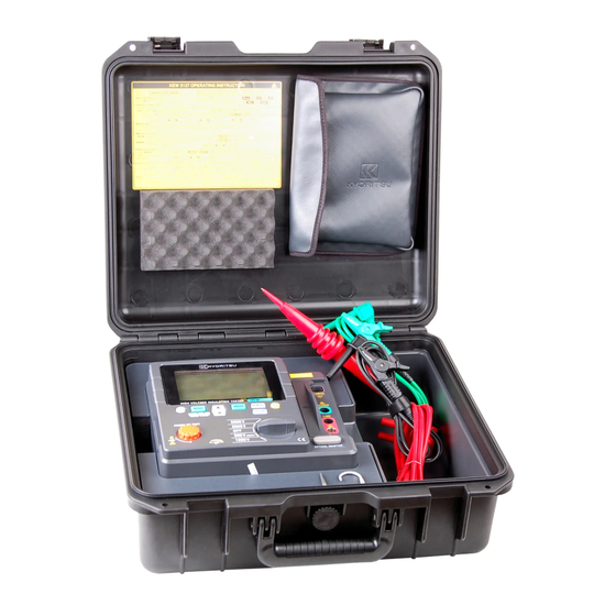
4-3 Opening and closing Hard case The Latching device has two features: the larger portion which is the latch itself ①, and the small latch release tab ② at the bottom of the latch. ① 1. To open, pull up the latch release tab ②... -
Page 16: Preparation For Measurement ・・・・・・・・・・・・・・・・・・・・・・・・・・・・・・・・・・・・・・・13
5. Preparation for measurement It is recommended to charge the battery with reference to 10.1 How to charge battery described in the manual before stating to use with the instrument since the battery voltage may be low due to self-discharge. 5-1 Checking the battery voltage (1) Set the Range switch to any position other than OFF . -
Page 17: Measurement ・・・・・・・・・・・・・・・・・・・・・・・・・・・・・・・・・・・・・・・・・・・・・・・・・・・・・14
6. Measurement 6-1 Mains disconnection check (Voltage measurement) # DANGER ● Do not make measurement on a circuit in which the electric potential exceeds 600V (voltage to ground) in order to avoid getting electrical shock. In addition, do not use this instrument when the voltage to ground is 600V or higher even the line voltage is 600V or less. -
Page 18: Insulation Resistance Measurement ・・・・・・・・・・・・・・・・・・・・・・・・・・・・・15
6-2 Insulation resistance measurement # DANGER ● Confi rm that no electrical charge exists on the circuit under test before measuring by using a high voltage detector. ● Put on a pair of insulated gloves for high voltage. ● In case the Range switch is set to Insulation resistance range, high voltage is being applied to the tips of test leads and to the circuit under test continuously while the Test button is kept pressed down. - Page 19 To check the insulation of electric equipments or electric circuits, measure their insulation resistances by using this instrument. Ensure to check the appropriate voltages to be applied to the equipment under test before starting a measurement. Note) ● KEW3127 may show unstable readings when the insulation resistance of the equipment under test is not stable.
- Page 20 (3) Connect the Earth cord (black) to the Earth terminal of the circuit under test. (4) Put the tip of the Line probe (red) to the circuit under test. Then press the Test button. The buzzer sounds intermittently during measurement when a range other than 500V(250V) range is selected. (5) The measured value will be displayed on the LCD, and it remains displayed on the LCD after a measurement.
- Page 21 (7) Set the Range switch to position, and remove test leads from the instrument. Note) ● The voltage warning mark stays on during a measurement and it blinks when voltages of AC/DC 30V or higher exist on the circuit under test. ●...
- Page 22 6-3 About BREAKDOWN mode and BURN mode Either Breakdown mode or Burn mode can be set for each measurement: IR PI/ DAR SV, DD, RAMP. (1) Breakdown mode When applied voltage decreases drastically due to breakdown or current sudden increase caused by insulation degradation, KEW3127 stops measurement automatically so as not to develop further damage.
- Page 23 6-4 Continuous measurement Press down and turn the Test button clockwise to lock it to perform a continuous measurement of insulation resistance. After testing, turn the button counterclockwise and set it to the initial position. # DANGER ● Be extremely careful not to get electric shock as high voltage is present on the tip of test leads continuously.
- Page 24 6-5 IR Measurement PI/DAR At IR measurement, PI/ DAR values are automatically calculated and PI/DAR displayed. During a measurement, values of current being measured and capacitances measured at discharging after measurement are displayed. Measurement Result PI/DAR Output voltage Resistance value During measurement: Output current Time when...
- Page 25 (2) Setting procedures Follow the procedures below [Stand-by state] ENTER button( Setting of Measurement duration (with UP/DOWN button ( ENTER button ( Setting of Output voltage*1 (with UP/DOWN button ( ENTER button ( Setting of Breakdown/Burn (with UP/DOWN button ( ...
- Page 26 6-5-2DAR - Dielectric Absorption Ratio DAR measurement is almost same to PI measurement in a sense that they test the time course of insulation. The only difference is that DAR measurement can get result faster than the other. Insulation resistance (1 min after a start of test) DAR = Insulation resistance...
- Page 27 When DAR/PI values are displayed as --- : DAR and PI values are determined by the methods 1. and 2. as described above, therefore, they are displayed as when the measured insulation resistances fall under any of following cases. ①measured value is 0.0MΩ...
- Page 28 6-5-4 How DAR/ PI values are displayed LCD shows DAR/PI values as shown below during measurements. (1) Start of test No DAR/PI value, “---” is displayed. (2) 1 min after the start of test DAR value is displayed. (3) 10 min after the start of test PI value is displayed.
- Page 29 6-5-5 How to review the measured DAR/PI values Press the UP/DOWN button ( ) when measurements end. The measured results are then displayed in following sequence. If the measurement ends earlier than the intervals described in below (2), (3) or (4), blank displays aren t shown and returns to (1).
-
Page 30: Sv Measurement (Step Voltage) ・・・・・・・・・・・・・・・・・・・・・・・・・・・・・・・27
6-6 SV Measurement (Step Voltage) This is a test based on the principle that an ideal insulation will produce identical readings at all voltages, while an insulation which is being over stressed, will show lower insulation values at higher voltages. During the test, the applied voltage incrementally steps by a certain voltage taking successive 5-time measurement. -
Page 31: Dd Measurement (Dielectric Discharge) ・・・・・・・・・・・・・・・・・・・・・・・・28
Setting procedures Follow the procedures below. [Stand-by state] ENTER button( Setting of Step time (with UP/DOWN button( ENTER button( Setting of Breakdown/Burn (with UP/DOWN button( ENTER button( Setting is finished. 6-7 DD Measurement (Dielectric Discharge) This measurement method is usually used to diagnosis multi-layer insulations, which requires the instrument to measure the discharge current and capacitance of the measured object 1 min after the removal of the test voltage. - Page 32 DD Measurement Result Output voltage Resistance value Discharge current or Time when Capacitance (switchable with a test ends UP/DOWN button DD or Voltage value (switchable with UP/DOWN button (1) Setting items Setting items for DD measurement are as follows. ...
-
Page 33: Ramp Measurement ・・・・・・・・・・・・・・・・・・・・・・・・・・・・・・・・・・・・・・・・・・30
6-8 Ramp Measurement Voltage used in Step voltage test is raised in steps but that used in Ramp measurement is gradually raised. Therefore, Ramp measurement is useful to fi nd the points of insulation failure without causing serious damages. This enables you to locate a fault, such as pinholes in windings, by seeing a spark or a wisp of smoke. - Page 34 (1) Setting items Setting items for RAMP measurement are as follows. (For RAMP measurement, 250V cannot be set at 500V (250V) Range.) * Speed of voltage rise: Voltage rise per minute. * Breakdown/ Burn : Either Breakdown or Burn mode is selectable. (2) Setting procedures ...
-
Page 35: Voltage Characteristics Of Measuring Terminal ・・・・・・・・・・・・・・・・・・・・32
6-9 Voltage characteristics of measuring terminal KEW3127 Output characteristics (IR mode) PI/DAR 6000 5000V range 5000 4000 3000 2500V range 2000 1000V range 1000 500V range 250V range 1000 1000 MΩ MΩ MΩ MΩ MΩ GΩ GΩ GΩ Insulation Resistance * for 10sec after a start of test 6-10 Use of Guard terminal When measuring the insulation resistance of a cable, leakage current flowing on... -
Page 36: Filter Function ・・・・・・・・・・・・・・・・・・・・・・・・・・・・・・・・・・・・・・・・・・・・・・・33
Conductor L Insulation Leakage current Power supply Protective wire G Indicator E Cable with sheath (Insulation resistance tester) 6-11 Filter function KEW3127 has Filter function. Filter Mode is effective to reduce the variations in readings due to external influences during high resistance measurements. The filter type is Low pass filter with cut off frequency of 0.3Hz. -
Page 37: Memory Function ・・・・・・・・・・・・・・・・・・・・・・・・・・・・・・・・・・・・・・・・・・・・・・・・・・34
7. Memory Function 7-1 Function Details Measurement data of insulation resistance can be saved in the internal memory of KEW3127. Following data can be saved. 1. LOGGING: Measuring data is saved every second. 2. MEMORY: Data is saved at the end of measurement. (1) Max number of file ... -
Page 38: How To Save Data ・・・・・・・・・・・・・・・・・・・・・・・・・・・・・・・・・・・・・・・・・・・・35
7-2 How to save data Follow the procedures below to save the measured data. Pressing the ESC button ( ), during operation, returns to the previous screen. (1) Stand-by state Data save in the MEMORY mode shall be done after fi nishing a measurement. ... -
Page 39: How To Recall Saved Data ・・・・・・・・・・・・・・・・・・・・・・・・・・・・・・・・・・・・・・36
7-3 How to recall saved data Follow the procedures below to recall the saved data. Pressing the ESC button ( ), during operation, returns to the previous screen. (1) Stand-by state (1s or longer) (2) Press the MEMORY button for 1 sec or longer. -
Page 40: How To Delete Data ・・・・・・・・・・・・・・・・・・・・・・・・・・・・・・・・・・・・・・・・・・・37
7-4 How to delete data Follow the procedures below to delete the saved data. Pressing the ESC button ( ), during operation, returns to the previous screen. Recall and display the data which one wishes to delete. (See clause 7-3 How to recall the saved data.) (1) Recall and display the saved data. -
Page 41: 8.Clock Setting ・・・・・・・・・・・・・・・・・・・・・・・・・・・・・・・・・・・・・・・・・・・・・・・・・・・・38
8.Clock Setting Follow the procedures below and adjust the internal clock of KEW3127. To confi rm the clock time, use the PC application KEW Windows or repeat the following steps. [Power-off state] (1) Hold down the ESC button and power on the instrument. -
Page 42: Communication Function/ Software ・・・・・・・・・・・・・・・・・・・・・・・・・・・・・・・・・・39
9. Communication Function/ Software 9-1 KEW3127 Settings The PC software application enables analysis of the saved data from PC. KEW3127 has following two kinds of communication methods. (1)Bluetooth (2)MODEL8212USB Following can be done via PC communication. (use software KEW Windows for KEW3127.) * Downloading a file in the internal memory of the instrument to a PC * Making settings for the instrument via PC. - Page 43 Instrument setting Follow the procedure below and select the communication method on KEW3127 before starting PC communication. (1) Hold down the ENTER button and power 1. [Power-off] state on the instrument. + Power on (2) LCD shows BT on . Use the UP/DOWN button ( ) and select a desirable 2.
- Page 44 After connecting MODEL 8212 Connect MODEL 8212 USB here. USB. (side view) ● Interface (1) Bluetooth Bluetooth Ver2.1+EDR (Class2) Compliant profi le: SPP (2 )MODEL8212USB Communication method: USB Ver1.1 ● Software KEW Windows for KEW3127 (Download this software from our homepage. Refer to 9-2 How to install the Software .) ●...
-
Page 45: How To Install The Software ・・・・・・・・・・・・・・・・・・・・・・・・・・・・・・・・・・・・42
9-2 How to install the Software Followings are the instructions to install the software KEW Windows and KEW Windows for KEW3127 . (1) Before installing the software, followings shall be checked. ● To prepare your system to install this software, please close all open programs. - Page 46 Enter the user information and specify the location to where install the software. Then click Next . Confirm the information on install, and click Install to start installing. - 43 -...
- Page 47 Click Finish when install completes. An installation of KEW Windows for KEW3127 is followed by the installation of KEW Windows . - 44 -...
- Page 48 ● To install the KEW Windows for KEW3127", you can follow the same installation procedure described for KEW Windows . If you need to remove this software, use the Add/Remove Programs tool in the Control Panel. 9-3 How to start KEW Windows for KEW3127 ●...
- Page 49 - 46 -...
-
Page 50: Features Of Kew Smart ・・・・・・・・・・・・・・・・・・・・・・・・・・・・・・・・・・・・・・・47
9-4 Features of KEW Smart Remote checking of measurements is possible without accessing KEW3127 using the special Android application KEW Smart . The application KEW Smart is available on download site for free. (An Internet access is required.) ... -
Page 51: 10.Battery Charging And Replacement ・・・・・・・・・・・・・・・・・・・・・・・・・・・・・・・48
10.Battery Charging and Replacement 10-1 How to charge battery # DANGER Use only the Power adapter supplied with this instrument. Connect the Power adapter to a mains socket outlet. The mains supply voltage must not exceed AC240V. Handling and storage instructions specifi ed by the battery manufacturer should be observed. -
Page 52: How To Replace Battery ・・・・・・・・・・・・・・・・・・・・・・・・・・・・・・・・・・・・・・・49
10-2 How to replace battery # DANGER ● Never open the battery compartment cover while making measurement. ● To avoid possible electric shock, disconnect the test lead and Power Adapter from the instrument before replacing battery. After replacing batteries, make sure to tighten up the screw for battery compartment cover. - Page 53 (3) Pull up the battery as below and disconnect the red and black cables. (Pull the positive and negative connectors upwards and disconnect them from the battery.) Pull the connector upwards. (4) Replace the old battery with the new one (lead-storage battery PXL-12050: 12V5Ah).
-
Page 54: Metal Part For Line Probe, And Replacement ・・・・・・・・・・・・・・・・・・・・・51
11.Accessories 11-1 Metal parts for Line Probe, and replacement # DANGER In the electrical environment of CAT.II or higher, MODEL8255 should be attached and used with the test lead. With the large exposed metal parts of MODEL8254 and 8019, the equipment under test may be shorted. It may result in failure of the equipment under test and cause fire or lead to fatal or serious injury. -
Page 55: How To Use The Adaptor For Recorder ・・・・・・・・・・・・・・・・・・・・・・・・・・・52
11-2 How to use the adaptor for recorder MODEL8302 is the adaptor for recorder (option) for output current measurement. Connect it as shown in the below fi gure. Output is DC1mA when current of 1μA is fl owing. To recorder -... -
Page 56: Disposing The Product ・・・・・・・・・・・・・・・・・・・・・・・・・・・・・・・・・・・・・・・・・・・・53
12. Disposing the Product Waste Electrical and Electronic Equipment (WEEE), Directive 2002/96/EC This Product complies with the WEEE Directive (2002/96/EC) marking requirement. The affixed product label (see below) indicates that you must not discard this electrical/electronic product in domestic household waste. Product Category With reference to the equipment types in the WEEE directive Annex 1, this product is classified as a... - Page 57 MEMO - 54 -...
- Page 58 MEMO - 55 -...
- Page 60 DISTRIBUTOR Kyoritsu reserves the rights to change specifications or designs described in this manual without notice and without obligations. 1-19 92-2156A...
Need help?
Do you have a question about the KEW 3127 and is the answer not in the manual?
Questions and answers