Aplex ARCHMI-8 H Series User Manual
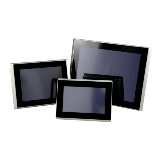
7”, 8”, 12.1”, and 15”intel celeron n2930, high brightness fanless industrial compact size panel pc
Hide thumbs
Also See for ARCHMI-8 H Series:
- User manual (140 pages) ,
- User manual (141 pages) ,
- User manual (100 pages)
Table of Contents
Advertisement
Quick Links
Electronic
Design
Why choose DSL?
• Over 25 Years
Industry Experience
• 5 Years Warranty
on all Products
• Evaluation Products Available
• Lifetime Technical Support
Call us on +44(0)1462 675330
Email us at sales@dsl-ltd.co.uk
Panel
Single Board
PC / HMI
Computer
Our Services
• Electronic Design
• Production Management
• Assembly and Test
• Bespoke BIOS Creation
• Industrial Embedded
PC Solutions
www.dsl-ltd.co.uk
Industrial
PC
Advertisement
Table of Contents

Related Manuals for Aplex ARCHMI-8 H Series


Summary of Contents for Aplex ARCHMI-8 H Series
- Page 1 Electronic Panel Single Board Industrial Design PC / HMI Computer Why choose DSL? Our Services • Over 25 Years • Electronic Design Industry Experience • Production Management • 5 Years Warranty • Assembly and Test on all Products • Bespoke BIOS Creation •...
- Page 2 Compact Size Panel PC User Manual Release Date Revision Jul. 2016 V1.1 ®2016 Aplex Technology, Inc. All Rights Reserved. Published in Taiwan Aplex Technology, Inc. 15F-1, No.186, Jian Yi Road, Zhonghe District, New Taipei City 235, Taiwan Tel: 886-2-82262881 Fax: 886-2-82262883 URL:...
-
Page 3: Revision History
Revision History Reversion Date Description 2016/06/20 Official Version 2016/07/19 Add 7”, 12.1”, and 15” HMI ARCHMI-8XX(P)H Series User Manual... -
Page 4: Warning
This information in this document is subject to change without notice. In no event shall Aplex Technology Inc. be liable for damages of any kind, whether incidental or consequential, arising from either the use or misuse of information in this document or in any related materials. -
Page 5: Packing List
Packing List Accessories (as ticked) included in this package are: □ Adaptor □ Driver & manual CD disc □ Other.___________________(please specify) ARCHMI-8XX(P)H Series User Manual... -
Page 6: Safety Precautions
Safety Precautions Follow the messages below to prevent your systems from damage: ◆ Avoid your system from static electricity on all occasions. ◆ Prevent electric shock. Don‘t touch any components of this card when the card is power-on. Always disconnect power when the system is not in use. -
Page 7: Table Of Contents
Table of Contents Revision History…………………………………………………………………………………………………….1 Warning!................…………………………….…2 Caution/Disclaimer……..……………………..…………………………………………………………………2 Packing List…………………………………….……………………………………………………………………..3 Safety Precautions…………………………………………………………………….…..……………………..4 Chapter 1 Getting Started 1.1 Features………………………..………………………...…………………………..7 1.2 Specifications…………………...………………………………………………….7 1.3 Dimensions………………………..…….………………………………………..9 1.4 Brief Description of ARCHMI-8XX(P)H..………………………….……12 1.5 Installation of HDD – 7” and 8”..…..…………...…………………..…..16 1.6 Installation of HDD – 12.1” and 15”….…………..…………………..-18 1.7 VESA Mounting…………………………………..………………………………20 1.8 Panel Mounting……………………………………..………………….……….20 Chapter 2... - Page 8 4.4 Realtek ALC662 HD Audio Driver Installation………………………67 4.5 USB 3.0 Driver…………………………………………………………………….68 4.6 Com Driver…..…………………………………………………………………….71 Chapter 5 Touch Screen Installation 5.1 Windows 7/8/8.1 Universal Driver Installation for PenMount 6000 Series…………………….…………….…………………………………...74 5.2 Software Functions…………………………………………………………..84 Figures Figure 1.1: Dimensions of ARCHMI-807(P)H……………………..…………………..…9 Figure 1.2: Dimensions of ARCHMI-808(P)H.…………………..……………….…...10 Figure 1.3: Dimensions of ARCHMI-812(P)H………………………………………..…10 Figure 1.4: Dimensions of ARCHMI-815(P)H……………………………………..……11 Figure 1.5: Front View of ARCHMI-807(P)H………………………..…………….……12...
-
Page 9: Getting Started
Chapter 1 Getting Started 1.1 Features 7”, 8”, 12.1”, and 15” Industrial Compact Size Panel PC Flat front panel touch screen Fanless design Intel Celeron N2930(1.83GHz) CPU built-in Onboard 4GB DDR3L 1600 MHz/8GB(option) 9~36VDC wide-ranging power input ... - Page 10 UPS Battery and TB-528 expansion board can’t be used in the same time for ARCHMI-812(P)H Storage Space Storage 1 x SD card slot, up to 32GB 1 x MO-297 SATA SSD bay (Easy Accessible) (for 7”/8”) 1 x 2.5" SATA HDD bay for SATA HDD (Easy Accessible) Expansion Expansion Slot 1 x Internal Mini-PCIe slot full size...
-
Page 11: Dimensions
ARCHMI-807(P)H ARCHMI-808(P)H ARCHMI-812(P)H ARCHMI-815(P)H Display Type 7” TFT LCD 8” TFT LCD 12.1” TFT LCD 15” TFT LCD Max. Resolution 800 x 480 800 x 600 800 x 600 1024 x 768 262K 16.2M 16.2M 16.2M Max. Color Luminance(cd/m²) 1000 1000 1000 1000... -
Page 12: Figure 1.2: Dimensions Of Archmi-808(P)H
Figure 1.2: Dimensions of ARCHMI-808(P)H Figure 1.3: Dimensions of ARCHMI-812(P)H ARCHMI-8XX(P)H Series User Manual... -
Page 13: Figure 1.4: Dimensions Of Archmi-815(P)H
Figure 1.4: Dimensions of ARCHMI-815(P)H ARCHMI-8XX(P)H Series User Manual... -
Page 14: Brief Description Of Archmi-8Xx(P)H
1.4 Brief Description of ARCHMI-8XX(P)H There are 7”, 8”, 12.1”, and 15” Industrial Compact Size Panel PC in ARCHMI-8XX(P)H series, which comes with flat front panel touch screen and fanless design. It is powered by Intel N2930(1.83GHz) processor built-in, and 4GB DDR3L 1600MHz memory (8GB memory is for option). -
Page 15: Figure 1.7: Front View Of Archmi-808(P)H
Figure 1.7: Front View of ARCHMI-808(P)H Figure 1.8: Rear View of ARCHMI-808(P)H ARCHMI-8XX(P)H Series User Manual... -
Page 16: Figure 1.9: Front View Of Archmi-812(P)H
Figure 1.9: Front View of ARCHMI-812(P)H Figure 1.10: Rear View of ARCHMI-812(P)H ARCHMI-8XX(P)H Series User Manual... -
Page 17: Figure 1.11: Front View Of Archmi-815(P)H
Figure 1.11: Front View of ARCHMI-815(P)H Figure 1.12: Rear View of ARCHMI-815(P)H ARCHMI-8XX(P)H Series User Manual... -
Page 18: Installation Of Hdd - 7" And 8
1.5 Installation of HDD – 7” and 8” Step 1 There are two screws to deal with when enclosing or removing the chassis. Gently remove two screws. Step 2 There is a SSD card in the bracket. Gently remove the screw, then carefully pull SSD card. - Page 19 Step 4 You can replace SSD card by unscrewing four screws as shown in the picture. Note: four screws are packed in the packing list. Step 5 There is a SD card hole in the side of the machine. You can replace SD card from there.
-
Page 20: Installation Of Hdd - 12.1" And 15
1.6 Installation of HDD – 12.1” and 15” Step 1 There are 2 screws to deal with when enclosing or removing the chassis. Gently remove 2 screws. Step 2 You can put or remove HDD into the machine by pulling the HDD bracket. Step 3 You can remove HDD by unscrewing 4 screws in the HDD bracket. - Page 21 Step 4 There is a SD hole in the side of machine. You can replace SD card from there ARCHMI-8XX(P)H Series User Manual...
-
Page 22: Vesa Mounting
1.7 VESA Mounting The ARCHMI-8XX(P)H is designed to be VESA mounted as shown in Picture. Just carefully place the unit through the hole and tighten the given screws from the rear to secure the mounting. Figure 1.13: ARCHMI-8XX(P)H VESA Mounting 1.8 Panel Mounting There are four holes located along the four sides of the HMI. -
Page 23: Chapter 2 Hardware
Chapter 2 Hardware 2.1 Motherboard Introduction SBC-7111 is a 4" industrial motherboard developed on the basis of Intel Bay trail-I/M Processors, which provides abundant peripheral interfaces to meet the needs of different customers. Also, it features dual GbE ports, 3-COM ports and one Mini PCIE configuration, one VGA port, one HDMI port, one LVDS interface. - Page 24 Storage 1 x SATAII Connector (7Pin, option) 1 x SATAII Connector (7Pin + 15Pin) 1 x SD Slot (USB2 to SD) Ethernet 2 x PCIe Gbe LAN by Intel 82574L USB 3.0 Hub(USB5534): 2 x USB 3.0/USB 2.0 (type A)stack ports (E2_USB5/E2_USB6) 1 x USB 2.0 Pin internal Touch controller (E2_USB7) 1 x USB 2.0 Pin header for CN1 (E2_USB8) USB 2.0 Hub(USB2514)
-
Page 25: Figure 2.1: Motherboard Dimensions
Switches and LED 1 x Power on/off switch (BT1/BT2/P_SW/CN2/CN3) Indicators 1 x Reset (CN2) 1 x Power LED status (CN1) 1 x HDD LED status (CN2) 1 x Buzzer External I/O port 2 x COM Ports (COM1/COM2) 2 x USB 3.0/2.0 Ports (stack) 2 x RJ45 GbE LAN Ports 1 x HDMI Port 1 x Stack audio Jack (Line out) -
Page 26: Jumpers And Connectors Location
2.3 Jumpers and Connectors Location Figure 2.2: Jumpers and Connectors Location- Board Top Figure 2.3: Jumpers and Connectors Location- Board Bottom ARCHMI-8XX(P)H Series User Manual... -
Page 27: Jumpers Setting And Connectors
2.4 Jumpers Setting and Connectors 1. U2: (FCBGA1170), onboard Intel Bay trail-I/M Processors. Model Processor Number Cores/Threads Remarks SBC-7111-N2930-4G SBC-7111-N2930-4G-SW N2930 1.83 up to 4 / 4 4.5 /7.5W SBC-7111-N2930P-4G 2.16GHz SBC-7111-N2930-2G SBC-7111-N2930P-CN3V-2G SBC-7111-N2930-8G SBC-7111-E3845-4G E3845 1.91GHz 4 / 4 option 2. - Page 28 Pin# Signal Name VBAT Ground 6. DC_IN1: (5.08mm Pitch 1x3 Pin Connector), DC9~36V System power input connector. Pin# Power Input DC+6V~36V Ground Model DC_IN1 SBC-7111-N2930-4G 180°Connector SBC-7111-N2930-4G-SW 180°Connector SBC-7111-N2930-2G 180°Connector SBC-7111-N2930-8G 180°Connector SBC-7111-E3845-4G 180°Connector SBC-7111-N2930P-4G 45°Connector SBC-7111-N2930P-CN3V-2G 45°Connector 7. DC_IN2 (option): (2.0mm Pitch 1x8 wafer Pin Header) DC12V System power input connector.
- Page 29 ● ● ○ SBC-7111-E3845-4G ○ ● ○ SBC-7111-N2930P-CN3V-2G SBC-7111-N2930-4G-SW ○ ● ● 9. FAN1(option): (2.54mm Pitch 1x3 Pin Header), Fan connector, cooling fans can be connected directly for use. You may set the rotation condition of cooling fan in menu of BIOS CMOS Setup.
- Page 30 CRT_V_SYNC CRT_DDCCLK Ground Ground VGA hot plug setting: VGA1 (Pin Header) Function Pin4-Pin6 (Close) VGA Simulation Disabled Pin4-Pin6 (Open) VGA Simulation Enabled Use the 2.0mm jumper cap to close pin4 and pin6 11. HDMI1: (HDMI 19P Connector), High Definition Multimedia Interface connector. 12.
- Page 31 14. INVT1: (2.0mm Pitch 1x6 wafer Pin Header), Backlight control connector for LVDS. Pin# Signal Name +DC12V +DC12V Ground Ground BKLT_EN_OUT BKLT_CTRL 15. CN1: (1.25mm Pitch 2x20 Connector, DF13-40P), for 18/24-bit LVDS output connector, fully supported by Parad PS8625(DP to LVDS), the interface features dual channel 24-bit output.
- Page 32 E2-USB8 E2-USB8_P E2-USB8_N 5V_S5_USB 5V_S5_USB Power LED PWR_LED+ Ground Power LED 16. JP4 (Reserve): (2.0mm Pitch 2x2 wafer Pin Header). Function Open 3-4 (default) Open 1-2 (default) Close 3-4 (option) Hardware Enabled 17. TCH1: (2.0mm Pitch 1x6 wafer Pin Header), internal Touch controller connector. Pin# Signal Name SENSE...
- Page 33 Function S_232 Pin# (switch) RS232 (Default) ON: Pin1, Pin2, Pin3, Pin4, Pin5 RS422 (option) OFF: Pin1, Pin2, Pin3, Pin4, Pin5 RS485 (option) OFF: Pin1, Pin2, Pin3, Pin4, Pin5 20. S_422: (Switch), COM1 setting, it provides selectable RS232 or RS422 or RS485 serial signal output.
- Page 34 Advanced/F81216SEC Super IO Configuration/Serial Port 1 Configuration 【RS-232】 RS422 (option) Pin# Signal Name 422_RX+ 422_RX- 422_TX- 422_TX+ Ground BIOS Setup: Advanced/F81216SEC Super IO Configuration/Serial Port 1 Configuration 【RS-422】 RS485 (option) Pin# Signal Name 485- 485+ Ground BIOS Setup: Advanced/F81216SEC Super IO Configuration/Serial Port 1 Configuration 【RS-485】 22.
- Page 35 23. COM2: (Type DB9M),Rear serial port, standard DB9 Male serial port is provided to make a direct connection to serial devices. Pin# Signal Name DCD# (Data Carrier Detect) RXD (Received Data) TXD (Transmit Data) DTR (Data Terminal Ready) Ground DSR (Data Set Ready) RTS (Request To Send) CTS (Clear To Send) JP2 select Setting (RI/5V/12V)
- Page 36 ○ SBC-7111-N2930P-CN3V-2G ○ SBC-7111-E3845-4G SBC-7111-N2930-2G ○ ○ SBC-711-N2930-8G 26. SATA2(option): (SATA 7Pin), SATA Connectors, one SATA connector are provided, with transfer speed up to 3.0Gb/s. Model SATA2 (Connectors) SBC-7111-N2930-4G ○ ○ SBC-7111-N2930-4G-SW ○ SBC-7111-N2930P-4G ○ SBC-7111-N2930P-CN3V-2G SBC-7111-E3845-4G ○ SBC-7111-N2930-2G ○ SBC-711-N2930-8G ○...
- Page 37 Signal Name Pin# Pin# Signal Name GND_AUD LINE-OUT-L LINE-OUT-R FRONT_JD LINE1_JD LINE_IN-L LINE-IN-R MIC-IN-L MIC-IN-R GND-AUD MIC1_JD 32. LINE_OUT1: (Diameter 3.5mm Jack), HD Audio port, an onboard Realtek ALC662-VD codec is used to provide high quality audio I/O ports. Line Out can be connected to a headphone or amplifier.
- Page 38 and ACTIVE LED (yellow) respectively located at the left-hand and right-hand side of the Ethernet port indicate the activity and transmission state of LAN. Model RJ45(LAN1) RJ45(LAN2) ● ● SBC-7111-N2930-4G SBC-7111-N2930P-4G ● ● ● ● SBC-7111-N2930-2G ● ● SBC-7111-N2930-8G ● ●...
- Page 39 Advanced/IT8518Super IO Configuration/Serial Port 1 Configuration【RS-485】 Advanced/IT8518Super IO Configuration/Serial Port 1 Configuration【RS-422】 Advanced/IT8518Super IO Configuration/Serial Port 2 Configuration【RS-485】 Advanced/IT8518Super IO Configuration/Serial Port 2 Configuration【RS-422】 37. EC_GPIO1(option): (2.0mm Pitch 1X10 Pin Header)For expand connector, it provides eight GPIO. Pin# Signal Name Ground GPA0_ONOFF GPA1_SPK-...
- Page 40 COM4_RI COM4_DCD- COM4 COM4 COM4_TXD COM4_RXD (UART) (UART) COM4_DTR RICOM4_RTS- COM4_DSR COM_CTS- Ground Ground COM3_RI COM3_DCD- COM3 COM3 COM3_TXD COM3_RXD (UART) (UART) COM3_DTR DSRCOM3_RTS- COM3_DSR DTRCOM3_CTS- GPIO23 SOC_GPIO23 ICH_GPIO22 GPIO12 GPIO25 SOC_GPIO25 ICH_GPIO24 GPIO24 Ground Ground PCIE_TX0_DN PCIE_TX0_DP PCIE_RX0_DN PCIE_RX0_DP PCIE 1X PCIE 1X Ground...
-
Page 41: Bios Setup
Chapter 3 BIOS Setup 3.1 Operations after POST Screen After CMOS discharge or BIOS flashing operation, press [Delete] key to enter CMOS Setup. After optimizing and exiting CMOS Setup, the POST screen displayed for the first time is as follows and includes basic information on BIOS, CPU, memory, and storage devices. -
Page 42: Main Settings
3.3 Main Settings System Time: Set the system time, the time format is: Hour : 0 to 23 Minute : 0 to 59 Second : 0 to 59 ARCHMI-8XX(P)H Series User Manual... -
Page 43: Advanced Settings
System Date: Set the system date, the date format is: Day: Note that the ‘Day’ automatically changes when you set the date. Month: 01 to 12 Date: 01 to 31 Year: 1998 to 2099 3.4 Advanced Settings 3.4.1 ACPI Settings Enable ACPI Auto Conf: [Disabled] [Enabled]... - Page 44 [Enabled] [Disabled] ACPI Sleep State: [S3 (Suspend to RAM) ] [Suspend Disabled] Lock Legacy Resources: [Disabled] [Enabled] 3.4.2 F81216SEC Super IO Configuration Super IO chip F81216SEC Serial Port 1 Configuration UART1 Mode Selection: [RS-232] [RS-485] [RS-422] Serial Port 2 Configuration Change Settings [Auto] Serial Port 3 Configuration...
- Page 45 3.4.5 CPU Configuration Socket 0 CPU Information Intel(R) Atom(TM) CPU E3845 @ 1.91GHz CPU Signature 30679 Microcode Patch Max CPU Speed 1910 MHz Mix CPU Speed 500 MHz Processor Cores Intel HT Technology Not Supported Intel HT-X Technology Supported L1 Data Cache 24KB x 4 L1 Code Cache 32KB x 4...
- Page 46 [Disabled] Max CPU C-state [C7] [C6] [C1] SOix [Disabled] [Enabled] 3.4.7 Thermal Configuration Parameters 3.4.8 IDE Configuration Serial-ATA(SATA) [Enabled] [Disabled] SATA Test Mode [Disabled] [Enabled] SATA Speed Support [Gen2] [Gen1] SATA ODD Port [No ODD] [Porto ODD] [Port1 ODD] [Disabled] SATA Mode [AHCI Mode] [IDE Mode]...
- Page 47 SATA Port1 Hotplug [Disabled] [Enabled] SATA Port0 Not Present SATA Port1 Not Present 3.4.9 Miscellaneous Configuration High Precision Timer [Enabled] [Disabled] Boot Timer with HPET Timer [Disabled] [Enabled] PCI Express Dynamic Clock Gating [Disabled] [Enabled] OS Selection Use the OS Selection option to select an operating system for the system. Note: Users must go to this item to select the OS mode before installing corresponding OS driver, otherwise problems will occur when installing the driver.
- Page 48 3.4.10 LPSS & SCC Configuration LPSS & SCC Configuration [ACPI Mode] SCC Configuration SCC eMMC Support [eMMC AUTO MODE] SCC eMMC 4.5 DDR50 Support [Enabled] SCC eMMC 4.5 HS200 Support [Disabled] eMMC Secure Erase [Disabled] SCC SDIO Support [Enabled] SCC SD Card Support [Enabled] SDR25 Support for SDCard [Disabled]...
- Page 49 CSM Support [Enabled] CSM16 Module Version 07.76 GateA20 Active [Upon Request] [Always] Option ROM Messages [Force BIOS] [Keep Current] Boot option filter [UEFI and Legacy] [Legacy only] [UEFI only] Network [UEFI] [Do not launch] [Legacy] Storage [UEFI] [Do not launch] [Legacy] Video [Legacy]...
- Page 50 EHCI Hand-off: [Disabled] [Enabled] USB Mass Storage Driver Support [Enabled] [Disabled] USB hardware delays and time-outs: USB transfer time-out: [20 sec] [10 sec] [5 sec] [1 sec] Device reset time-out: [20 sec] [10 sec] [30 sec] [40 sec] Device power-up delay [Auto] [Manual] 3.4.67 Platform Trust Technology...
-
Page 51: Chipset Settings
3.5 Chipset Settings 3.5.1 Host Bridge ►Intel IGD Configuration ►IGD – LCD Control Force Lid Status [On] [Off] [Auto] ALS Support [Disabled] IGD Flat Panel [Auto] Pannel Scaling [Auto] ►Memory Frequency and Timing ►Graphics Power Management Control Memory Information Total Memory 4096 MB(DDR3L) ARCHMI-8XX(P)H Series User Manual... - Page 52 Memory Slot0 2048 MB(DDR3L) DIMM#1 2048 MB(DDR3L) Max TOLUD [Dynamic] [2GB] [2.25GB] [2.5GB] [2.75GB] [3GB] Backlight PWM or DC Control [PWM] [DC] Backlight PWM Control [PWM Normal by BIOS] BIOS Control Backlight Level [Level 7] [Level 0] [Level 1] [Level 2] [Level 3] [Level 4] [Level 5]...
-
Page 53: Security Settings
►Azalia HD Audio ►USB Configuration USB OTG Support [Disabled] USB VBUS [On] XHCI Mode [Smart Auto] USB2 Link Power Management [Enabled] USB 2.0(EHCI) Support [Enabled] USB EHCI debug [Disabled] USB Per Port Control [Enabled] USB Port 0 [Enabled] USB Port 1 [Enabled] USB Port 2 [Enabled]... - Page 54 3.6.2 User Password Type the password with up to 20 characters and then press Enter key. This will clear all previously typed CMOS passwords. You will be requested to confirm the password. Type the password again and press Enter key. You may press key to abandon password entry operation.
-
Page 55: Boot Settings
3.7 Boot Settings Setup Prompt Timeout Bootup Numlock State [On] [off] Quiet Boot [Disabled] [Enabled] Fast Boot [Disabled] [Enabled] Boot Option Priorities Boot Option #1 Sets the system boot order Hard Drive BBS Priorities [SATA PM:*** … ] Boot Option #1 SATA PM:***…... -
Page 56: Save & Exit Settings
Disabled 3.8 Save & Exit Settings Save Changes and Exit Save & Exit Setup save Configuration and exit ? [Yes] [No] Discard Changes and Ext Exit Without Saving Quit without saving? [Yes] [No] Save Changes and Reset Save & reset Save Configuration and reset? [Yes] [No] Discard Changes and Reset... - Page 57 Reset Without Saving Reset without saving? [Yes] [No] Save Changes Save Setup Values Save configuration? [Yes] [No] Discard Changes Load Previous Values Load Previous Values? [Yes] [No] Restore Defaults Load Optimized Defaults Load optimized Defaults? [Yes] [No] Save user Defaults Save Values as User Defaults Save configuration? [Yes] [No]...
-
Page 58: Chapter 4 Installation Of Drivers
Chapter 4 Installation of Drivers This chapter describes the installation procedures for software and drivers under the windows 7. The software and drivers are included with the motherboard. The contents include Intel chipset driver, VGA driver, LAN drivers, Audio driver, USB 3.0 Driver, and Com Driver Installation instructions are given below. -
Page 59: Intel(R) Atomtm Soc Chipset
4.1 Intel(R) AtomTM SoC Chipset To install the Intel chipset driver, please follow the steps below. Step 1. Select Intel (R) AtomTM SoC Chipset from the list Step 2. Click Next to setup program. ARCHMI-8XX(P)H Series User Manual... - Page 60 Step 3. Read the license agreement. Click Yes to accept all of the terms of the license agreement. Step 4. Click Next to continue. ARCHMI-8XX(P)H Series User Manual...
- Page 61 Step 5. Click Next. Step 6. Select Yes, I want to restart this computer now. Click Finish, then remove any installation media from the drives. ARCHMI-8XX(P)H Series User Manual...
-
Page 62: Intel(R) Vga Chipset
4.2 Intel(R) VGA Chipset To install the VGA drivers, follow the steps below to proceed with the installation. Step 1.Select Intel(R) VGA Chipset Step 2. Click Automatically run WinSAT and enable the Windows Aero desktop theme(if supported). Click Next. ARCHMI-8XX(P)H Series User Manual... - Page 63 Step 3. Read license agreement. Click Yes. Step 4. Click Next. ARCHMI-8XX(P)H Series User Manual...
- Page 64 Step 5. Click Install. Step 6. Click Install. ARCHMI-8XX(P)H Series User Manual...
- Page 65 Step 7. Click Next. Step 8. Click Yes, I want to restart this computer now. Then click Finish. ARCHMI-8XX(P)H Series User Manual...
-
Page 66: Intel(R) Lan Driver
4.3 Intel(R) LAN Driver To install the Intel (R) LAN driver, please follow the steps below. Step 1. Select Intel(R) 82574L LAN Driver from the list. Step 2. . Click Next. ARCHMI-8XX(P)H Series User Manual... - Page 67 Step 3. Read license agreement. Click I accept the terms in the license agreement. Click Next. Step 4. Click Next to continue. ARCHMI-8XX(P)H Series User Manual...
- Page 68 Step 5. Click Install to begin the installation. Step 6. Click Finish to exit the wizard. ARCHMI-8XX(P)H Series User Manual...
-
Page 69: Realtek Alc662 Hd Audio Driver Installation
4.4 Realtek ALC662 HD Audio Driver Installation To install the Realtek ALC662 HD Audio Driver, please follow the steps below. Step 1. Select Realtek AL662 HD Audio Driver from the list Step 2. Click Next to continue. ARCHMI-8XX(P)H Series User Manual... -
Page 70: Usb 3.0 Driver
Step 3. Click Yes, I want to restart my computer now. Click Finish to complete the installation. 4.5 USB 3.0 Driver To install the USB 3.0 Driver, please follow the steps below. Step 1. Select USB 3.0 Driver from the list ARCHMI-8XX(P)H Series User Manual... - Page 71 Step 2. Click Next to continue. Step 3. Read the license agreement. Then click Yes to continue. ARCHMI-8XX(P)H Series User Manual...
- Page 72 Step 4. Click Next to continue. Step 5. Click Next to continue. ARCHMI-8XX(P)H Series User Manual...
-
Page 73: Com Driver
Step 6. Select Yes, I want to restart this computer now. Then click Finish to complete the installation. 4.6 Com Driver To install the Com Driver, please follow the steps below. Step 1. Select Com Driver from the list ARCHMI-8XX(P)H Series User Manual... - Page 74 Step 2. Click Next to continue. Step 3. Click install to begin the installation. ARCHMI-8XX(P)H Series User Manual...
- Page 75 Step 4. Click Finish to complete the installation. ARCHMI-8XX(P)H Series User Manual...
-
Page 76: Chapter 5 Touch Screen Installation
Chapter 5 Touch Screen Installation This chapter describes how to install drivers and other software that will allow your touch screen work with different operating systems. 5.1 Windows 7/8/8.1 Universal Driver Installation for PenMount 6000 Series Before installing the Windows 7/8/8.1 driver software, you must have the Windows 7/8/8.1 system installed and running on your computer. - Page 77 Step 2. Select Resistive Touch. Step 3. Click Next to continue. ARCHMI-8XX(P)H Series User Manual...
- Page 78 Step 4. Read the license agreement. Click I Agree to agree the license agreement. Step 5. Choose the folder in which to install PenMount Windows Universal Driver. Click Install to start the installation. ARCHMI-8XX(P)H Series User Manual...
- Page 79 Step 6. Click Yes to continue. Step 7. Click Finish to complete installation. ARCHMI-8XX(P)H Series User Manual...
- Page 80 5.1.2 Installing Software (Projected Capacitive) Step 1. Insert the product CD, the screen below would appear. Click touch panel driver. Step 2. Select Projected Capacitive. ARCHMI-8XX(P)H Series User Manual...
- Page 81 Step 3. Click Next to continue. Step 4. Select I accept the terms of the license agreement. Click Next. ARCHMI-8XX(P)H Series User Manual...
- Page 82 Step.5. Click Next to continue. Step 6. Click Install RS232 interface driver. ARCHMI-8XX(P)H Series User Manual...
- Page 83 Step 7. Select None. Click Next. Step 8. Click OK. Step 9. Click Support Muti-Monitor System. Click Next. ARCHMI-8XX(P)H Series User Manual...
- Page 84 Step 10. Go to C:\Program Files\eGalaxTouch. Click Next. Step 11. Click Next. ARCHMI-8XX(P)H Series User Manual...
- Page 85 Step 12. Click Create a eGalaxTouch Utility shortcut on desktop. Click Next. Step 13. Wait for installation. Step 14. Click Yes to do 4 point calibration. ARCHMI-8XX(P)H Series User Manual...
-
Page 86: Software Functions
5.2 Software Functions 5.2.1 Software Functions(Resistive Touch) Upon rebooting, the computer automatically finds the new 6000 controller board. The touch screen is connected but not calibrated. Follow the procedures below to carry out calibration. 1. After installation, click the PenMount Monitor icon “PM” in the menu bar. 2. - Page 87 Standard Calibration Click this button and arrows appear pointing to red squares. Use your finger or stylus to touch the red squares in sequence. After the fifth red point calibration is complete. To skip, press ‘ESC’. Advanced Calibration Advanced Calibration uses 4, 9, 16 or 25 points to effectively calibrate touch panel linearity of aged touch screens.
- Page 88 Step 2.Click “Standard Calibration” to start calibration procedure NOTE: The older the touch screen, the more Advanced Mode calibration points you need for an accurate calibration. Use a stylus during Advanced Calibration for greater accuracy. Please follow the step as below: ARCHMI-8XX(P)H Series User Manual...
- Page 89 Step 3. Select Device to calibrate, then you can start to do Advanced Calibration. NOTE: Recommend to use a stylus during Advanced Calibration for greater accuracy. Plot Calibration Data Check this function and a touch panel linearity comparison graph appears when you have finished Advanced Calibration.
- Page 90 Setting Touch Mode This mode enables and disables the mouse’s ability to drag on-screen icons – useful for configuring POS terminals. Mouse Emulation – Select this mode and the mouse functions as normal and allows dragging of icons. Click on Touch – Select this mode and mouse only provides a click function, and dragging is disables.
- Page 91 Edge Compensation You can use Edge Compensation to calibrate more subtly. ARCHMI-8XX(P)H Series User Manual...
- Page 92 About This panel displays information about the PenMount controller and driver version. Multiple Monitors Multiple Monitors support from two to six touch screen displays for one system. The PenMount drivers for Windows 7/8/8.1 support Multiple Monitors. This function supports from two to six touch screen displays for one system. Each monitor requires its own PenMount touch screen control board, either installed inside the display or in a central unit.
- Page 93 1. Check the Enable Multiple Monitor Support box; then click Map Touch Screens to assign touch controllers to displays. 2. When the mapping screen message appears, click OK. 3. Touch each screen as it displays “Please touch this monitor”. Following this sequence and touching each screen is called mapping the touch screens.
- Page 94 6. “Touch this screen to start its calibration” appears on one of the screens. Touch the screen. 7. “Touch the red square” messages appear. Touch the red squares in sequence. 8. Continue calibration for each monitor by clicking Standard Calibration and touching the red squares.
- Page 95 PenMount Monitor has the following function Control Panel Open Control Panel Windows Beep Setting Beep function for each device Right Button When you select this function, a mouse icon appears in the right-bottom of the screen. Click this icon to switch between Right and Left Button functions.
- Page 96 5.2.2 Software Functions(Projected Capacitive) General In this window, you can see there is USB Controller. Click OK to continue. Monitor Mapping to adjust touch panel to search for device ARCHMI-8XX(P)H Series User Manual...
- Page 97 Setting Beep Beep On Touch Beep On Release Beep From System Beep Beep From Sound Card Linearization Style 9 points 25 points Double Click Time Shorter Longer Double Click Area Smaller Bigger Normal mode Simulate the mouse mode ARCHMI-8XX(P)H Series User Manual...
- Page 98 Option Function Enable Constant Touch Enable Auto Right Click Enable Touch Enable Cursor Stabilization Constant Touch Area Auto Right Click Time ARCHMI-8XX(P)H Series User Manual...
- Page 99 Tools Click OK to continue the settings. 4 Points Calibration Do 4 points alignment to match display. Clear and Calibrate Clear linearization parameter and do 4 points alignment. Linearization Do 9 points linearization for better touchscreen linearity. Draw Test Do draw test to verify the touch accuracy. ARCHMI-8XX(P)H Series User Manual...
- Page 100 Display In this window, it shows the mode of display. Enable Multiple Monitors. Map to main display if system has only one display monitor Full Screen Lower Screen Left Screen Upper Screen Right Screen ARCHMI-8XX(P)H Series User Manual...
- Page 101 Other Other mode of display. Quarter1~4 and Customized area. Active Area Drag active area to enable Active Area Function. ARCHMI-8XX(P)H Series User Manual...
- Page 102 Hardware Saturn Hardware Configuration ARCHMI-8XX(P)H Series User Manual...
- Page 103 About To display information about eGalaxTouch and its version. ARCHMI-8XX(P)H Series User Manual...
Need help?
Do you have a question about the ARCHMI-8 H Series and is the answer not in the manual?
Questions and answers