Table of Contents
Advertisement
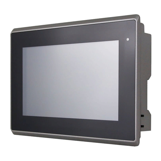
ARCHMI-8XX Series
7", 8", 10.1", 12.1", 15", 15.6", 17", 18.5", 19" and 21.5" Intel Atom E3845/Celeron
N2930, Fanless Industrial Compact Size Panel PC
User Manual
Release Date
Revision
Mar. 2017
V1.7
®2016 Aplex Technology, Inc.
All Rights Reserved.
Published in Taiwan
Aplex Technology, Inc.
15F-1, No.186, Jian Yi Road, Zhonghe District, New Taipei City 235, Taiwan
Tel: 886-2-82262881 Fax: 886-2-82262883 URL:
www.aplextec.com
Advertisement
Table of Contents


Need help?
Do you have a question about the ARCHMI-807 and is the answer not in the manual?
Questions and answers