Table of Contents
Advertisement
Quick Links
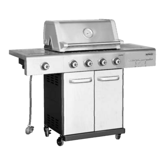
Assembly and Operating Instructions for Outback®
Jupiter 4S and Jupiter 6S Gas BBQ
RS4491SC
Drawings are not to scale.
Specifications subject to change
without prior notice.
For outdoor use only. Not for commercial use.
Read instructions before using the appliance. Failure to follow instructions could
result in death, serious bodily injury, and/or property loss.
Warning: accessible parts may be very hot. Keep young children and pets away.
Do not move the appliance during use.
Turn off the gas supply at the gas bottle after use.
Any modification of the appliance, misuse, or failure to follow the instructions may
be dangerous and will invalidate your warranty. This does not affect your statutory
WARNING
rights.
Retain these instructions for future reference.
Leak test annually, and whenever the gas bottle is removed or replaced. Check that
the hose connections are tight and leak test each time you reconnect the gas bottle.
For Flare-up control please refer to the 'OPERATION' section of this manual.
FOR YOUR SAFETY
If you smell gas:
1.
Shut off gas to the appliance.
2.
Extinguish any open flame.
3.
Open barbecue lid or hood.
4.
If odour continues, discontinue use and
contact your local dealer.
RS5691SC
FOR YOUR SAFETY
1.
Do not store or use petrol or other flammable
vapours or liquids in the vicinity of this or any
other appliance.
2.
A gas bottle not connected for use must not be
stored in the vicinity of this or any other
appliance.
0359
Advertisement
Table of Contents

Related Manuals for Outback RS4491SC


Summary of Contents for Outback RS4491SC
- Page 1 Assembly and Operating Instructions for Outback® Jupiter 4S and Jupiter 6S Gas BBQ RS4491SC RS5691SC Drawings are not to scale. Specifications subject to change 0359 without prior notice. For outdoor use only. Not for commercial use. Read instructions before using the appliance. Failure to follow instructions could result in death, serious bodily injury, and/or property loss.
-
Page 2: Parts List
Parts List Quantity varies according to model purchased. Specifications subject to change without prior notice. For more details on hardware, please see the corresponding ‘Hardware Reference Diagram’. CODE PART Jupiter 4S Gas BBQ Jupiter 6S Gas BBQ Hood (Pre-Assembled to Body) ... -
Page 3: Parts Diagram
Parts Diagram Quantity varies according to model purchased. Specifications subject to change without prior notice. For more details on hardware, please see the corresponding ‘Hardware Reference Diagram’. - Page 4 Hardware Reference Diagram Specifications subject to change without prior notice.
- Page 5 Assembly IMPORTANT! TOOLS NEEDED FOR ASSEMBLY: Medium size flat blade or Phillips/Crosspoint screwdriver, adjustable spanner or metric spanner set. Remove any internal component or packaging from the barbecue body. Whilst every care is taken in the manufacture of this product, care must be taken during assembly in ...
- Page 6 Attach the Food Basket Bracket (C25x2pcs) onto the Middle Panel (C24) using M6x15 Bolts (D2x4pcs), Then attach the middle panel assembly to the cabinet assembly using M6x15 Bolts (D2x5pcs) as shown. Attach the Storage Unit (C23) onto the Bottom Panel (C21) using M6x15 Bolts (D2x4pcs) as shown.
- Page 7 Attach the Food Basket Front Bracket (C27) to the Left Cabinet Panel Assembly (C14) and Middle Panel (C24) using M6x15 Bolts (D2x4pcs). Attach the Upper Support (C16) to the left/right cabinet panel assembly using M6x15 Bolts (D2x4pcs).
- Page 8 Attach the Front Wheel Skirt (C22) onto the Bottom Panel (C21) using M6x15 Bolts (D2x3pcs) as shown. Carefully turn the cabinet upside-down. Attach the Casters (C29) and Lockable Casters (C28) onto the left/right cabinet panels as shown. Ensure the lockable casters are installed on the rear side.
- Page 9 Remove the retaining bolts from one Door Handle (C17), then attach the door handle onto the Left Door (C18) using the retaining bolts as shown. Repeat above process for Right Door (C19). Fit the doors to the cabinet by depressing the spring pins and placing into the cabinet.
- Page 10 Carefully place the Barbecue Body (B1) onto the cabinet assembly and fix using M6x15 Bolts (D2x4pcs) as shown. Attach Side Shelf Panel (C4) onto Side Shelf (C3) using M6x15 Bolts (D2x2pcs) and M6 Nut (D6x2pcs) as shown.
- Page 11 step1 step2 step3 step4 Attach the side shelf assembly to the barbecue body using ST4.0x10 Screw (D5x2pcs) and M6x15 Bolts (D2x4pcs) as shown. Attach Side Burner Shelf Panel (C2) onto Side Burner Shelf (C1) using M6x15 Bolts (D2x2pcs) and M6 Nut (D6x2pcs) as shown.
- Page 12 step1 step2 step4 step3 Attach the side burner shelf assembly to the barbecue body using ST4.0x10 Screw (D5x2pcs) and M6x15 Bolts (D2x4pcs) as shown. Attach the Side Burner Firebox (C8) into the side burner shelf using M4x10 Bolts (D7x4pcs) as shown.
- Page 13 Attach Side Burner Electrode (C9) into the side burner firebox using a ST4.0x10 Screws F# (D3) as shown. Connect the electrode wire to the ignitor. WARNING: BEFORE OPERATION, ENSURE SIDE BURNER WIRES ARE CONNECTED TO IGNITOR. IF THE CIRCUIT IS NOT COMPLETED, THE IGNITOR WILL NOT SPARK! Attach the side burner valve and Knob Bezel (C10) onto side burner shelf using M4x10 Bolts (D7x2pcs) as shown.
- Page 14 Feed the tube of the Sear Burner (C12) through the guide hole in the side burner firebox, and fix it using M5x15 Bolt (D4x2pcs) as shown. Make sure that the end of tube is set over the gas outlet of side burner valve. Attach Side Burner Lid (C6) onto the side burner shelf using Side Burner Lid Axle (C7) as shown.
- Page 15 Place the Side Burner Grid (C5) onto the side burner shelf. NOTE: Only use cookware with a base diameter of between 150mm and 220mm on the side burner. Insert the Side Burner Drip Tray (C13) by sliding it underneath the side burner frame as shown.
- Page 16 Insert the Drip Tray (B9) by sliding it underneath the barbecue body. Lay the Flame Tamer (B6) carefully into the body ensuring it lies level within the body. Lay the Cooking Grill (B8) and Round Grill (B7) into place. Lay the Chopping Board (C32) into the Side Shelf.
- Page 17 Attach the Warming Rack (A3) to the Barbecue Body (B1) as shown. Insert the Hook Rail (C31) through the Tool Hooks (C30) as shown, then fix the assembly onto side shelf panel using M5x10 Bolts (D8x2pcs).
- Page 18 Attach the Food Basket (C26) to the cabinet as shown. ASSEMBLY IS NOW COMPLETE.
-
Page 19: Leak Testing
1. Maximum diameter or breadth is 320mm. 2. Maximum height (regulator included) is 700mm. PROCEED TO THE NEXT PAGE FOR INSTRUCTIONS ON OPERATION AND MAINTENANCE ALL JOINTS AND CONNECTIONS MUST NOW BE LEAK TESTED BEFORE USING THE BARBECUE. Leak test annually, and whenever the gas bottle is removed or replaced. Leak Testing Always perform a leak test in a well-ventilated area. -
Page 20: Gas, Regulator And Hose
leak test. This is the only safe and sure way Important Information to detect any gas leaking from joints and connections of the barbecue after assembly. Please read these instructions carefully before assembly and use of your barbecue. Leak test annually, and whenever the gas bottle is removed or replaced. -
Page 21: Installation
of heat and damage the barbecue. This is Installation not covered by warranty. Selecting a Location Preparation Before Cooking This barbecue is for outdoor use only and To prevent foods from sticking to the cooking should be placed in a well-ventilated area, and surface, please use a long handled brush to on a safe and even surface. - Page 22 Open the gas control valve on the gas bottle baking food, such as joints of meat or whole chickens, etc. More even cooking of food will or regulator. Insert lit match through the right match- actually be achieved by using the barbecue with the hood down.
-
Page 23: Care And Maintenance
extinguished by applying baking soda or salt Care and Maintenance directly onto the flame tamers . Always protect your hands when handling anything near the Regularly clean your barbecue between uses cooking surface of the barbecue and take care and especially after extended periods of to protect yourself from the flames. - Page 24 (debris, insects) in either the burner portholes or Stainless Steel the primary air inlet of the burners. Use a pipe Stainless Steel is a type of steel containing chromium, which offers high resistance cleaner to clear obstructions. corrosion and heat by forming a protective layer of Chromium Oxide.
-
Page 25: Technical Specifications
Technical Specifications NOTES: Heat Injector Burners Approval Input Size Consumption Outback® 0359 12.96 Butane: 943g/hr Jupiter 4S 0.89mm 359BR665 Propane: 926g/hr Gas BBQ Outback® 0359 19.44 Butane: 1415g/hr Jupiter 6S 0.89mm 359BR665 Propane: 1390g/hr Gas BBQ Side 0359 Butane: 328g/hr 1.04mm... -
Page 26: Troubleshooting
Troubleshooting Problem Possible Cause Solution Burner will not light using LP gas bottle is empty Replace with full bottle the ignition system Faulty regulator Have regulator checked or replaced Obstructions in burner Clean burner Obstructions in gas jets or gas hose Clean jets and gas hose Electrode wire is loose is connected on Reconnect wire... - Page 27 Other parts are warranted for a period of one (1) year from the date of purchase. OUTBACK® will, within above periods, supply replacements for defective parts free of charge provided that: The product has not been used for trade, professional or hire purposes.
Need help?
Do you have a question about the RS4491SC and is the answer not in the manual?
Questions and answers