Advertisement
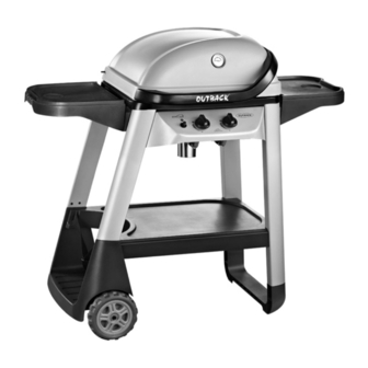
Assembly and Operating Instructions for Outback®
Excel 210, and Excel 310 Gas Barbecues
Photographs are not to scale.
Specifications subject to change
without prior notice.
WARNING
For Flare-up control please refer to the 'OPERATION' section of this manual.
FOR YOUR SAFETY
If you smell gas:
1.
Shut off gas to the appliance.
2.
Extinguish any open flame.
3.
Open barbecue lid or hood.
4.
If odour continues, discontinue use and
contact your local dealer.
EX210T
For outdoor use only. Not for commercial use.
Read instructions before using the appliance. Failure to follow instructions
could result in death, serious bodily injury, and/or property loss.
Warning: accessible parts may be very hot. Keep young children and pets
away.
Do not move the appliance during use.
Turn off the gas supply at the gas bottle after use.
Any modification of the appliance, misuse, or failure to follow the instructions
may be dangerous and will invalidate your warranty. This does not affect your
statutory rights.
Retain these instructions for future reference.
Leak test annually, and whenever the gas bottle is removed or replaced. Check
that the hose connections are tight and leak test each time you reconnect the
gas bottle.
EX310T
FOR YOUR SAFETY
1.
Do
not
store or
flammable vapours or liquids in the vicinity
of this or any other appliance.
2.
A gas bottle not connected for use must not
be stored in the vicinity of this or any other
appliance.
0359
use petrol
or other
Advertisement
Table of Contents

Related Manuals for Outback Outback Excel 210


Summary of Contents for Outback Outback Excel 210
- Page 1 Assembly and Operating Instructions for Outback® Excel 210, and Excel 310 Gas Barbecues EX310T EX210T Photographs are not to scale. Specifications subject to change 0359 without prior notice. For outdoor use only. Not for commercial use. Read instructions before using the appliance. Failure to follow instructions could result in death, serious bodily injury, and/or property loss.
-
Page 2: Parts List
Parts List Quantity varies according to model purchased. Specifications subject to change without prior notice. For more details on hardware, please see the corresponding ‘Hardware Reference Diagram’. OUTBACK® OUTBACK® CODE PART EXCEL 210 GAS EXCEL 310 GAS √ √ Hood (Pre-Assembled to Body) ... - Page 3 Parts Diagram: Excel 210 Quantity varies according to model purchased. Specifications subject to change without prior notice. For more details on hardware, please see the corresponding ‘Hardware Reference Diagram’.
- Page 4 Hardware Reference Diagram: Excel 210 Specifications subject to change without prior notice.
- Page 5 Parts Diagram: Excel 310 Quantity varies according to model purchased. Specifications subject to change without prior notice. For more details on hardware, please see the corresponding ‘Hardware Reference Diagram’.
- Page 6 Hardware Reference Diagram: Excel 310 Specifications subject to change without prior notice.
- Page 7 Assembly IMPORTANT! TOOLS NEEDED FOR ASSEMBLY: Medium size flat blade or Phillips/Crosspoint screwdriver, adjustable spanner or metric spanner set. The assembly of this barbecue requires 2 people. Whilst every care is taken in the manufacture of this product, care must be taken during assembly in ...
- Page 8 Excel 210 Excel 310 Attach the Bottom Shelf (C20) to the Gas Bottle Holder (C15) using ST4.8x15 Screws (D6). Take care not to over tighten these screws which will damage the plastic gas bottle holder. Note: This step assembly requires 2 people. Excel 210 Excel 310...
- Page 9 Excel 210 Excel 310 Insert the Axle (C19) through the clamping brackets underneath the Gas Bottle Holder (C15) and tighten the clamping screws. Slide the Wheels (C18) over Take care not to over tighten these screws which will damage the each end of the axle.
- Page 10 Excel 210 Excel 310 a. Unscrew the nut from the Heat Indicator(A4). Place the heat indicator through the hole on the top of Hood(A1). Tighten the heat indicator with the nut. b. Attach the Hood Handle (A2) to the Hood (A1) using the M5x10 Bolts (D2).
- Page 11 Excel 210 Excel 310 Install a M6x15 Bolt (D1) and a Spacer (D9) into the upper fixing hole on each front leg. Place the Control Panel (B3) assembly in position by aligning the spacers with the slot on each side of control panel and fix it to the trolley assembly using M6x15 Bolts (D1). Excel 210 Excel 310...
- Page 12 Excel 210 Excel 310 Insert the Main Electrode (B10) into the hole at the bottom of the barbecue body and secure with the pre-assembled nut. Excel 210 Excel 310 View from underneath the body Feed the Burner (B2) into barbecue body. Ensure that the burner venturi tubes are over the ends of the gas valves.
- Page 13 Excel 210 Excel 310 Attach the Body Heat Shield (B12) to barbecue body using the M5x10 Bolts (D2) and M5 Nuts (D8). Excel 210 Excel 310 Carefully lay the Lava Rock (B6) into the barbecue body ensuring it lies level within the body.
- Page 14 Excel 210 Excel 310 Step 1 Step 2 Step 3 Step 4 Attach the Warming Rack (A3), to the hood and barbecue body as shown. Make sure that the shorter, fixed legs go through the holes in the hood, then the swing legs fix to the body of the barbecue.
- Page 15 Excel 210 Excel 310 Slide a Shelf Spacer (D9) onto a M6x15 Bolt (D1) and screw it into the upper fixing point on the rear legs as shown. Repeat for the front leg. Attach the assembled Side Shelf (C2) to the right hand side of the barbecue by sliding a Shelf Spacer (D9) onto a M6x15 Bolt (D1) and fitting the shelf to the lower fixing point on the rear leg as shown.
- Page 16 Excel 210 Excel 310 Excel 210 users, skip this step and proceed directly to step 23. Attach the Side Burner Shelf (C7) to the left front and left rear legs using M6x15 Bolts (D1). Excel 210 Excel 310 Remove the screws from Side Burner Valve / Hose Assembly (C10) and secure it to the side shelf with those 2 screws.
- Page 17 Excel 210 Excel 310 Place the Side Burner Electrode (C9) onto the side burner shelf as shown. Place the Side Burner (C8) through the central hole. Fit the side burner venturi tube over the gas valve outlet. This is a loose fit and not a gas tight seal.
- Page 18 Excel 210 Excel 310 Excel 310 users, skip this step and proceed directly to step 24. Fix the Hose Clip (D10) into the lower hole of the front short leg using a ST4.0x10 Screw (D4), then feed the hose through the clip as shown. Important: Regularly check the hose positioning to ensure that it is not in contact with any hot sur- faces, such as the bottom of the body or the heat shield.
-
Page 19: Leak Testing
Leak Test Diagram 1. Maximum diameter or breadth is 315mm. 2. Maximum height (regulator included) is 580mm. ASSEMBLY IS NOW COMPLETE. PROCEED TO THE NEXT PAGE FOR INSTRUCTIONS ON OPERATION AND MAINTENANCE ALL JOINTS AND CONNECTIONS MUST NOW BE LEAK TESTED BEFORE USING THE BARBECUE. - Page 20 Important Information Before you use your barbecue, perform a leak test. This is the only safe and sure way to detect any gas leaking from joints and Please read these instructions carefully connections of the barbecue after assembly. before assembly and use of your barbecue. Leak test annually, and whenever the gas ...
-
Page 21: Installation
local gas dealer for the most suitable regulators Preparation Before Cooking and gas bottles. To prevent foods from sticking to the cooking surface, please use a long handled brush to apply a light coat of cooking or vegetable oil Installation before each barbecuing session. - Page 22 dealer for assistance. before grilling, use cooking sauces and After ignition, turn the burners to the low marinades sparingly and try to avoid very position for 3-5 minutes in order to pre-heat cheap cuts of meat or meat products as these tend to have a high fat and water the barbecue.
-
Page 23: Care And Maintenance
Provided that they are operating correctly, in barbecue covers and other accessories are normal usage, burning off the residue after available from your local Outback® stockist. cooking will keep the burners clean. Even when your barbecue is covered for its... - Page 24 Do not let children burners in order to burn off any residue. tamper with the bottle. Replacement lava rock is available from your local Outback® stockist. When using the barbecue after extended periods storage follow...
-
Page 25: Technical Specifications
Technical Specifications Notes: Heat Injector Burners Gas /Pressure Approval Input Size Outback® 0359 Butane: 28-30mbar Excel 210 6.6kW 0.89mm 359BS791 Propane: 37mbar Outback® 0359 Butane: 28-30mbar Excel 310 6.6kW 0.89mm 359BS791 Propane: 37mbar Side Butane: 28-30mbar 2.3kW 0.74mm Burner 359BS791... -
Page 26: Troubleshooting
Troubleshooting Problem Possible Cause Solution Burner will not light using LP gas bottle is empty Replace with full bottle the ignition system Faulty regulator Have regulator checked or replaced Obstructions in burner Clean burner Obstructions in gas jets or gas hose Clean jets and gas hose Electrode or ignition button wire is loose Reconnect wire... - Page 27 OUTBACK® WARRANTY OUTBACK® barbecues are warranted for a period of one (1) year from the date of purchase to the original purchaser against defects in materials and workmanship, OUTBACK® will sup- ply replacements for defective parts free of charge provided that: The product has not been used for trade, professional or hire purposes.
Need help?
Do you have a question about the Outback Excel 210 and is the answer not in the manual?
Questions and answers