Table of Contents
Advertisement
Quick Links
Photographs are not to scale.
Specifications subject to change
without prior notice.
WARNING
FOR YOUR SAFETY
If you smell gas:
1. Shut off gas to the appliance.
2. Extinguish any open flame.
3. Open barbecue lid or hood.
4. If odour continues, discontinue use and contact
your local dealer.
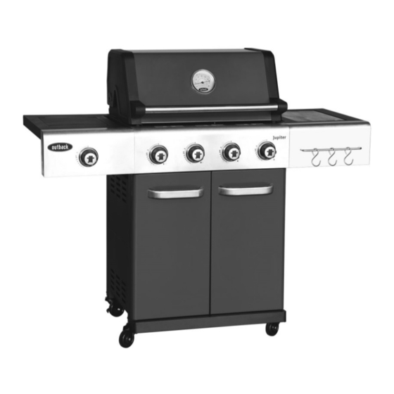
Assembly and Operating Instructions for
®
Outback
Jupiter 4 Gas/Charcoal Hybrid
For outdoor use only. Not for commercial use.
Read instructions before using the appliance. Failure to follow instructions could
result in death, serious bodily injury, and/or property loss.
Warning: accessible parts may be very hot. Keep young children and pets away.
Do not move the appliance during use.
Turn off the gas supply at the gas bottle after use.
Any modification of the appliance, misuse, or failure to follow the instructions
may be dangerous and will invalidate your warranty. This does not affect your
statutory rights.
Retain these instructions for future reference.
Leak test annually, and whenever the gas bottle is removed or replaced. Check
that the hose connections are tight and leak test each time you reconnect the
gas bottle.
For Flare-up control please refer to the 'OPERATION' section of this manual.
RS4491H
FOR YOUR SAFETY
1. Do not store or use petrol or other flammable
vapours or liquids in the vicinity of this or any
other appliance.
2. A gas bottle not connected for use shall not be
stored in the vicinity of this or any other
appliance.
2575
0359
Advertisement
Table of Contents

Related Manuals for Outback Jupiter RS4491H


Summary of Contents for Outback Jupiter RS4491H
- Page 1 Assembly and Operating Instructions for ® Outback Jupiter 4 Gas/Charcoal Hybrid RS4491H Photographs are not to scale. Specifications subject to change 2575 0359 without prior notice. For outdoor use only. Not for commercial use. Read instructions before using the appliance. Failure to follow instructions could result in death, serious bodily injury, and/or property loss.
-
Page 2: Parts List
Parts List Quantity varies according to model purchased. Specifications subject to change without prior notice. For more details on hardware, please see the corresponding ‗Hardware Reference Diagram‘. Jupiter 4 Gas/ CODE PART Charcoal Hybrid Hood (Pre-Assembled to Body) Hood Handle ... -
Page 3: Parts Diagram
Parts Diagram Quantity varies according to model purchased. Specifications subject to change without prior notice. For more details on hardware, please see the corresponding ‗Hardware Reference Diagram‘. - Page 4 Hardware Reference Diagram Specifications subject to change without prior notice.
- Page 5 Assembly IMPORTANT! TOOLS NEEDED FOR ASSEMBLY: Medium size flat blade or Phillips/Crosspoint screwdriver, adjustable spanner or metric spanner set. Remove any internal component or packaging from the barbecue body. Whilst every care is taken in the manufacture of this product, care must be taken during assembly in ...
- Page 6 Attach the Rear Panels (C16x2pcs) to the cabinet assembly using ST4.0x10 Screws (D2x11pcs) as shown. Attach the Upper Support (C12) to the left/right cabinet panel using M6x15 Bolts (D3x4pcs).
- Page 7 Carefully turn the cabinet upside-down. Attach the Casters (C20x2pcs) and Lockable Casters (C21x2pcs) onto the left/right cabinet panels as shown. Ensure the lockable casters are installed on the rear side. Remove the retaining bolts from one Door Handle (C13), and then attach the door handle onto the Left Door (C14) using the retaining bolts as shown.
- Page 8 Fit the doors to the cabinet by depressing the spring pins and placing into the cabinet. Carefully place the Barbecue Body (B1) onto the cabinet assembly and fix it using M6x15 Bolts (D3x4pcs) as shown.
- Page 9 Attach Side Shelf Panel (C4) onto Side Shelf (C3) using M6x15 Bolts (D3x2pcs) and M6 Nuts (D4x2pcs) as shown. step1 step2 step3 step4 Attach the side shelf assembly to the barbecue body using ST4.0x10 Screws (D2x2pcs) and M6x15 Bolts (D3x4pcs) as shown.
- Page 10 Attach Side Burner Shelf Panel (C2) onto Side Burner Shelf (C1) using M6x15 Bolts (D3x2pcs) and M6 Nuts (D4x2pcs) as shown. step1 step2 step4 step3 Attach the side burner shelf assembly to the barbecue body using ST4.0x10 Screws (D2x2pcs) and M6x15 Bolts (D3x4pcs) as shown.
- Page 11 Side burner Valve Attach the side burner valve and Knob Bezel (C7) onto side burner shelf using M4x10 Bolts (D5x2pcs) as shown. Press the Side Burner Knob (C8) onto side burner valve stem. Feed the venturi tube of the Side Burner (C9) through the hole in bottom of the side burner shelf, and fix it onto side burner shelf using a M4x10 Bolt (D5) as shown.
- Page 12 Electrode wire Connect the side burner electrode wire to the ignitor on side burner valve. WARNING: BEFORE OPERATION, ENSURE SIDE BURNER WIRES ARE CONNECTED TO IGNITOR. IF THE CIRCUIT IS NOT COMPLETED, THE IGNITOR WILL NOT SPARK! Lay the Flame Tamers (B6) carefully into the body ensuring it lies level within the body. Lay the Cooking Grills (B8) and Round Grill (B7) into place.
- Page 13 Attach the Warming Rack (A4) to the barbecue body as shown. Insert the Drip Tray (B9) by sliding it underneath the barbecue body.
- Page 14 Insert the Hook Rail (C22) through the Tool Hooks (C5) as shown, then fix the assembly onto side shelf panel using M5x10 Bolts (D6x2pcs) . Lay the Clapboard (C19) on the brackets inside of cabinet and slide it to the end as shown.
-
Page 15: Leak Testing
1. Maximum diameter or breadth is 320mm. 2. Maximum height (regulator included) is 700mm. ASSEMBLY IS NOW COMPLETE. PROCEED TO THE NEXT PAGE FOR INSTRUCTIONS ON OPERATION AND MAINTENANCE ALL JOINTS AND CONNECTIONS MUST NOW BE LEAK TESTED BEFORE USING THE BARBECUE. -
Page 16: Gas, Regulator And Hose
Important Information to detect any gas leaking from joints and connections of the barbecue after assembly. Please read these instructions carefully Leak test annually, and whenever the gas before assembly and use of your barbecue. bottle is removed or replaced. ... -
Page 17: Installation
WARRANTY. In the case of replacing your solid plate — this includes baking dishes. original hose and regulator, please consult your Full coverage will cause excessive build-up local gas dealer for the most suitable regulators of heat and damage the barbecue. This is and gas bottles. - Page 18 or regulator. done with the burners on low. Insert lit match through the right match- For best results, place the food you wish to lighting hole on the right side of the bake or roast on a metal baking tray and set it barbecue body and place near rightmost on one side of the cooking grill.
-
Page 19: Care And Maintenance
given below. hands. Never douse the barbecue with water when Fat Fires its surfaces are hot. Empty and clean the drip tray and drip pan (and foil liner, if applicable) of food debris after each In order to extend the life and maintain the cooking session. - Page 20 surface with a plastic or wooden scraper or Do not use a wire brush, steel wool or brass wire brush. Do not use a steel scraper or abrasives as these will strip the protective wire brush. Clean with hot soapy water and layer, which can lead to rusting.
-
Page 21: Technical Specifications
Technical Specifications NOTES: Heat Injector Burners Input Size Consumption ® Outback Jupiter 4 Gas/ Butane:943g/hr 12.96kW 0.89mm Charcoal Propane:926g/hr Hybrid Butane:214g/hr Side Burner 2.94kW 0.84mm Propane:210g/hr CE Approval Pin Number: 2575DM30422 UKCA Approval Pin Number: 0359BR665 Category: I 3+ (28-30/37) -
Page 22: Troubleshooting
Troubleshooting Problem Possible Cause Solution Burner will not light using LP gas bottle is empty Replace with full bottle the ignition system Faulty regulator Have regulator checked or replaced Obstructions in burner Clean burner Obstructions in gas jets or gas hose Clean jets and gas hose Electrode wire is loose is connected on Reconnect wire... - Page 23 The product has not sustained damage through foreign objects, substances or accidents. The care and maintenance instructions given in your Outback manual have been followed. If the product includes one or a number of parts or accessories, only the defective accessory or part will be replaced i.e.
Need help?
Do you have a question about the Jupiter RS4491H and is the answer not in the manual?
Questions and answers