Sign In
Upload
Manuals
Brands
Mellanox Technologies Manuals
Switch
SX6710
Mellanox Technologies SX6710 Manuals
Manuals and User Guides for Mellanox Technologies SX6710. We have
4
Mellanox Technologies SX6710 manuals available for free PDF download: Hardware User Manual, Quick Installation Manual, Quick Start Manual
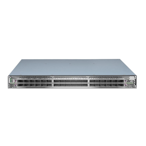
Mellanox Technologies SX6710 Hardware User Manual (112 pages)
SX67X0 series. 1U Switch Systems
Brand:
Mellanox Technologies
| Category:
Switch
| Size: 4.73 MB
Table of Contents
Table of Contents
3
Revision History
8
Table 1: Revision History Table
8
About this Manual
9
Table 2: References
9
Chapter 1 Introduction to Mellanox SX67X0 Systems
10
Overview
10
Figure 1: SX67X0 Front Side View
10
Speed and Switching
11
Management Interfaces and Frus
11
Figure 2: SX6710/SX6720 Rear Side View
11
Figure 3: SX6730 Rear Side View
11
Figure 4: SX6790 Rear Side View
11
Table 3: Speed and Switching Capabilities
11
Table 4: Management Interfaces and Frus
11
Features
12
Certifications
12
Ordering Information
12
Table 5: Ordering Part Numbers (Opns)
12
Chapter 2 Installation
13
Safety Warnings
13
Air Flow
14
Table 6: Air Flow Color Legend
14
Package Contents
15
Figure 5: Air Flow Direction Marking - Power Side Inlet to Connector Side Outlet
15
Figure 6: Air Flow Direction Marking - Connector Side Inlet to Power Side Outlet
15
Figure 7: SX6730 Air Flow Direction - Power Side Inlet to Connector Side Outlet
15
Mounting Options
17
Battery Backup Unit (BBU) Installation for SX6720
17
Figure 8: Unlocking the Latches and Extracting the PSU
18
Figure 9: BBU Location
18
Figure 10: BBU Insertion (Left) and Extraction (Right)
19
Mounting Options
20
19" Systems Mounting - Static Rail-Kit
20
Table 7: Installation Kit
20
Figure 11: Rack Rail Kit Parts
21
Figure 12: Installation Options
22
Figure 13: Attaching the Rails to the Chassis
22
Figure 14: Attaching the Brackets to the Chassis
23
Figure 15: Attaching the Brackets to the Rack
23
Figure 16: Sliding the Blades in the Rails
24
19" Systems Mounting- Telescopic Rail-Kit
25
Table 8: Installation Kit
25
Figure 17: Rack Rail Kit Parts
26
Figure 18: Rails Separation
26
Figure 19: Mounting the Outer Rails into the Rack
27
Figure 20: Attaching the Inner Rails to the Chassis
28
Figure 21: Securing the Chassis in the Inner Rails
28
Figure 22: Sliding the Switch into the Rack
29
Figure 23: Pulling the Unit Outwards
29
Cable Installation
30
Figure 24: Locking Mechanism
30
Figure 25: Cable Orientation
31
Using a Breakout Cable
31
Figure 26: Breakout or Fanout Cable
32
Table 9: Port Splitting Options
32
Initial Power on
34
Figure 27: System Status Leds 5 Minutes after Power on
34
Bring-Up of Managed Systems
35
Configuring Network Attributes
35
Figure 28: Two Power Inlets - Electric Caution Notifications
35
Table 10: Serial Terminal Program Configuration
36
Table 11: Configuration Wizard Session
37
Table 12: Configuration Wizard Session - Static IP Configuration
38
Remote Connection
39
FRU Replacements
40
Power Supply
40
Fans
41
Figure 29: PS Unit Pulled out
41
Figure 30: Fan Module Latches
42
Chapter 3 Software Management
43
Infiniband Subnet Manager
43
Fabric Inspector (Diagnostics)
43
Upgrading Software (on Managed Systems)
44
Chapter 4 Interfaces
45
Supported Interfaces
45
Data Interfaces
45
Speed
45
RS232 (Console)
45
Management
46
Usb
46
Reset Button
46
Leds
47
LED Notifications
47
Table 13: Leds Symbols
47
Figure 31: System Status Leds - Front and Rear Sides
48
Figure 32: Fan Status LED - Front and Rear Sides
48
Table 14: System Status LED Assignments
48
Figure 33: Power Status LED
49
Table 15: Fan Status Front LED Assignments
49
Table 16: Fan Status Rear LED Assignments (One LED Per Fan)
49
Figure 34: Rear Side Panel
50
Table 17: Power Supply Unit Status Front LED Assignments
50
Table 18: Power Supply Unit Status Rear LED Assignments
50
Table 19: Bad Port LED Assignments
51
Figure 35: Port Leds
52
Table 20: Port Leds in Infiniband System Mode
52
Inventory Pull-Out Tab
53
Chapter 5 Troubleshooting
54
Troubleshooting Instructions
54
Table 21: Troubleshooting
54
Chapter 6 Specifications
56
SX67X0 Series
56
Table 22: SX67X0 Specifications
56
Appendix A Accessory and Replacement Parts
58
Appendix B Thermal Threshold Definitions
58
Table 23: Opns for Replacement Parts
58
Appendix C Interface Specifications
59
QSFP Interface
59
RJ-45 CONSOLE and I²C Interface
61
RJ45 to DB9 Harness Pinout
61
Table 24: RJ-45 CONSOLE and I²C Pinout
61
Appendix D Disassembly and Disposal
62
Disassembly Procedure
62
Appendix E Safety Warnings (Multiple Languages)
63
Nordic Countries Notices
63
Installation Safety Warnings (English)
63
安裝安全性警告 (Chinese)
71
Avertissements de Sécurité Pour L'installation (French)
77
Installation Sicherheitshinweise(German)
81
Advertencias de Seguridad de Instalación (Spanish)
85
Предупреждения По Технике Безопасности При Установке (Russian)
90
Avertismente Privind Siguranţa la Instalare (Romanian)
94
Sigurnosna Upozorenja Za Instaliranje (Croatian)
99
Avvertenze DI Sicurezza Per L'installazione (Italiano)
103
Montaj Güvenlik Uyarıları (Türkçe)
108
Advertisement
Mellanox Technologies SX6710 Hardware User Manual (110 pages)
SwitchX-2 1U Switch Systems
Brand:
Mellanox Technologies
| Category:
Switch
| Size: 3.89 MB
Table of Contents
Table of Contents
3
Table 1: Revision History Table
8
Table 2: References
9
Chapter 1 Introduction to Mellanox SX67X0/SX6710G Systems
11
Overview
11
Speed and Switching
12
Management Interfaces, Psus and Fans
12
Features
12
Certifications
12
Table 3: Speed and Switching Capabilities
12
Table 4: Management Interfaces, Psus and Fans
12
Figure 1: SX67X0/SX6710G Front Side View
12
Figure 2: SX67X0/SX6710G Rear Side View
12
Ordering Information
13
Table 5: Ordering Part Numbers (Opns)
13
Chapter 2 Installation
14
Safety Warnings
14
System Installation and Initialization
15
Air Flow
15
Package Contents
16
Table 6: Air Flow Color Legend
16
Figure 3: Air Flow Direction Marking - Power Side Inlet to Connector Side Outlet
16
Figure 4: Air Flow Direction Marking - Connector Side Inlet to Power Side Outlet
16
Battery Backup Unit (BBU) Installation for SX6720
18
Installing the Battery
18
Extracting the Battery
19
Figure 5: Unlocking the Latches and Extracting the PSU
19
Figure 6: BBU Location
19
Mounting Options
20
Static Rail Kit
20
Table 7: Installation Kit
20
Figure 7: BBU Insertion (Left) and Extraction (Right)
20
Figure 8: Rack Rail Kit Parts
21
Figure 9: Installation Options
22
Figure 10: Attaching the Rails to the Chassis
23
Figure 11: Attaching the Brackets to the Chassis
23
Figure 12: Installing the Cage Nuts
24
Figure 13: Attaching the Brackets to the Rack
24
Telescopic Rail Kit
25
Figure 14: Sliding the Blades in the Rails
25
Table 8: Installation Kit
26
Figure 15: Rack Rail Kit Parts
27
Figure 16: Rails Separation
28
Figure 17: Installing the Cage Nuts
28
Figure 18: Mounting the Outer Rails into the Rack
29
Figure 19: Attaching the Inner Rails to the Chassis
29
Figure 20: Securing the Chassis in the Inner Rails
29
Figure 21: Sliding the Switch into the Rack
30
Figure 22: Pulling the Unit Outwards
31
Figure 23: Locking Mechanism
31
Cable Installation
32
Breakout Cables and Adapters
32
Figure 24: Cable Orientation
32
Table 9: Port Splitting Options
33
Figure 25: Breakout or Fanout Cable
33
Figure 26: SX67X0 Splitting Options
33
Initial Power on
34
System Bring-Up
35
Configuring Network Attributes
35
Figure 27: System Status Leds 5 Minutes after Power on
35
Figure 28: Two Power Inlets - Electric Caution Notifications
35
Table 10: Serial Terminal Program Configuration
36
Table 11: Configuration Wizard Session
36
Table 12: Configuration Wizard Session - Static IP Configuration
38
FRU Replacements
41
Power Supply
41
Figure 29: PS Unit Pulled out
41
Fans
42
Figure 30: Fan Module Latches
42
Chapter 3 Interfaces
43
Supported Interfaces
43
Data Interfaces
43
Speed
43
RS232 (Console)
44
Management
44
Usb
44
Reset Button
44
Status and Port Leds
45
Leds
45
LED Notifications
45
Table 13: Leds Symbols
45
Table 14: System Status LED Assignments
46
Figure 31: System Status Leds - Front and Rear Sides
46
Figure 32: Fan Status LED- Front and Rear Sides
46
Table 15: Fan Status Rear LED Assignments (One LED Per Fan)
47
Figure 33: Power Status LED
47
Figure 34: Rear Side Panel
47
Table 16: Power Supply Unit Status Front LED Assignments
48
Table 17: Power Supply Unit Status Rear LED Assignments
48
Table 18: Bad Port LED Assignments
49
Table 19: BBU LED Assignments
49
Figure 35: Port Leds
49
Inventory Information
50
Table 20: Port Leds in Infiniband System Mode
50
Chapter 4 Software Management
52
Infiniband Subnet Manager
52
Fabric Inspector (Diagnostics)
52
Upgrading Software (on Managed Systems)
53
MLNX-OS Software Upgrade
53
Switch Firmware Update
53
Chapter 5 Troubleshooting
54
Troubleshooting Instructions
54
Table 21: Troubleshooting
54
Chapter 6 Specifications
56
SX67X0/SX6710G Series
56
Table 22: SX67X0/SX6710G Specifications
56
Table 23: Opns for Replacement Parts
57
Table 24: QSFP Interface Pins 1-23
59
Table 25: QSFP Interface Pins 24-38
60
Mellanox Technologies SX6710 Quick Installation Manual (8 pages)
InfiniBand 1U Switch Systems
Brand:
Mellanox Technologies
| Category:
Switch
| Size: 1.84 MB
Advertisement
Mellanox Technologies SX6710 Quick Start Manual (2 pages)
Air Duct Rail Kit
Brand:
Mellanox Technologies
| Category:
Computer Hardware
| Size: 0.75 MB
Advertisement
Related Products
Mellanox Technologies SX6518-6R
Mellanox Technologies SX6518-NR
Mellanox Technologies SX67X0
Mellanox Technologies SX6720
Mellanox Technologies SX6710G
Mellanox Technologies SX6730
Mellanox Technologies SX6790
Mellanox Technologies SX6036
Mellanox Technologies SX6518
Mellanox Technologies SX1036
Mellanox Technologies Categories
Switch
Computer Hardware
Adapter
Network Card
Network Router
More Mellanox Technologies Manuals
Login
Sign In
OR
Sign in with Facebook
Sign in with Google
Upload manual
Upload from disk
Upload from URL