
Related Manuals for ACME DVS-2500


Summary of Contents for ACME DVS-2500
- Page 1 DigiVideo Spot DVS-2500/DVS-5000/DVS-5000II User Guide Please read these instructions carefully before use...
- Page 2 DVS-2500/5000/5000II...
-
Page 3: Table Of Contents
DVS-2500/5000/5000II CONTENTS 1. Safety Instruction ....................... 2. Installation ..........................3. Technical Specification ....................4. Description ..........................4.1 Description of the fixture ..............11 4.2 Control Panel ..................12 5. Lamp ............................6. How To Set The Unit ...................... 6.1 Display Status When Power On ............14 6.2 Main Function .................. -
Page 4: Safety Instruction
DVS-2500/5000/5000II 1. Safety Instruction Please read carefully the instruction manual which includes important information about the installation usage and maintenance. WARNIN Please keep this User Manual for future consultation. If you sell the unit to another user, be sure that they also receive this instruction manual. - Page 5 DVS-2500/5000/5000II replacing bulb or maintenance as it could be very hot. Avoid any inflammable liquids, water or metal objects entering the unit. Once it happens, cut off the mains power immediately. Do not operate in dirty or dusty environment; do clean the fixture regularly.
-
Page 6: Installation
DVS-2500/5000/5000II Product Items Digital Video Spot 2500/5000 User manual 2 x Omega clamps 8GB memory SD card (packaged with user manual) 2. Installation 1. Bolt each clamp (1) to the Omega holder with screw and lock nut through the hole in the holder. - Page 7 DVS-2500/5000/5000II Fig.3 Attention: Always ensure that the structure to which you are attaching the unit is secure and is able to support a weight of 10 times of the unit’s weight. Also always use a safety cable that can hold 12 times of the weight of the unit when installing the fixture.
-
Page 8: Technical Specification
- Beam angle: 24 degree (DVS-2500); 30 degree (DVS-5000) - Light output(ANSI Lumens):2500(DVS-2500); 3600(DVS-5000) - Contrast Ratio (Typical Full on/ Full off): 1800:1(DVS-2500); 2600:1(DVS-5000) - Display technology: DLP by Texas Instruments - Lamp: Osram E20.8 180W (DVS-2500) , HRI 280W (DVS-5000)Lamp... - Page 9 DVS-2500/5000/5000II port - Supported image file types: JPG (Image resolution is 720 x 480px) - Supported video file types: AVI, MJPEG (From SD card: 720 x 480) (From computer: 800 x 600 ) Shutter - Blackout Cool - Fan cooled...
- Page 10 DVS-2500/5000/5000II DMX Channels Mode Mode 1 Mode 2 Channel 54-CH 29-CH Pan Fine Pan Fine Tilt Tilt Tilt Fine Tilt Fine Pan/Tilt Speed Pan/Tilt Speed Pan/Tilt Macro Shutter Shutter Picture/Video Picture/Video Video Number Video Number Video Speed Video Speed Layer1 Picture Directory /Color...
- Page 11 DVS-2500/5000/5000II Layer3 Center Offset Layer3 Center Rotation Layer3 X Zoom Layer3 Y Zoom Layer3 Zoom Macro Layer3 Rotation Picture Macro Picture Macro Center Offset Picture Macro Center Rotation Picture Macro X Zoom Picture Macro Y Zoom Picture Macro Zoom Macro...
-
Page 12: Description
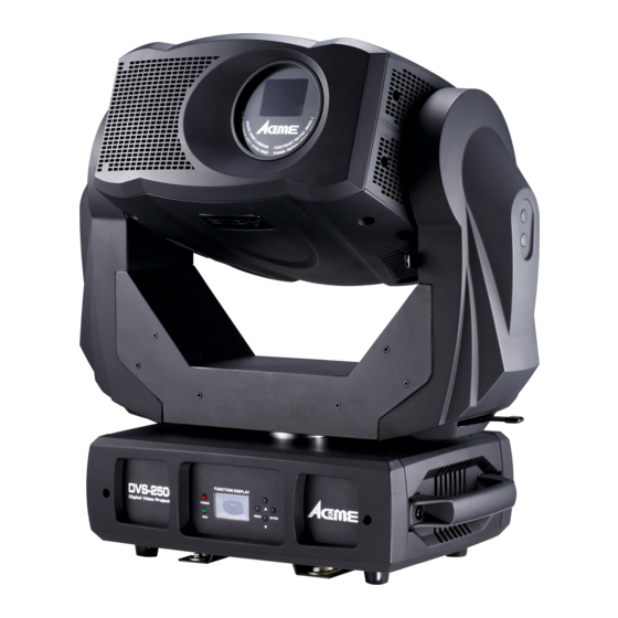
DVS-2500/5000/5000II 4. Description 4.1 Description of the fixture 1. Head 2. Tilt lock 3. Pan lock 4. Front panel 5. Memory card slot 6. Arm 7. Handle 8. Back panel For transportation protection, please set the tilt lock/unlock (2) and the pan lock/unlock lever (3) in the lock position before any transportations. -
Page 13: Control Panel
DVS-2500/5000/5000II 4.2 Control Panel Front View Rear View ○ 1 LCD Display: shows the various menus and the selected functions. ○ POWER Power on DMX input present ○ 3 Antenna W-DMX wireless receiver receive signal from a wide range. ○... -
Page 14: Lamp
DVS-2500/5000/5000II ○ 8 Power Cable: To connect to the mains AC outlet ○ 9 Fuse (T 6.3 A): Protect the unit from damage of over current. 5. Lamp Osram E20.8 180W or HRI 280W Lamp Because of its high internal pressure, there might be a risk that the discharge lamp would explode during operation. -
Page 15: How To Set The Unit
Every time you turn on the unit, it will run built-in program to reset all motors to their home position, the display will show as fig.4(DVS-2500), you may hear some noises for about 20 seconds. It will show warning sign if it goes wrong during resetting and you can press the MENU button to view the error information. -
Page 16: Main Function
DVS-2500/5000/5000II Explanation of fig.5: Base 30°C Present temperature of base CPU is 30°C Present DMX start address Md.1 54Ch Present channel mode is mode 1 (54 channels mode) Warning signal blinking indicates resetting error, press Enter for more details. 6.2 Main Function Turn on the unit, press MENU button into menu mode, press UP and DOWN button until the required function is shown on the monitor. - Page 17 DVS-2500/5000/5000II...
- Page 18 DVS-2500/5000/5000II DMX Settings Enter menu mode, select DMX Settings, press ENTER button to confirm, press UP/DOWN button to select DMX Address, DMX Channel Mode, View DMX Value or WDMX Setting DMX Address—DMX512 address setting Select DMX Address, press ENTER button to confirm, the present address will blink on the display, press UP/DOWN button to adjust the address from 1 to 512, press ENTER button to store.
- Page 19 DVS-2500/5000/5000II DMX Channel Mode—channel mode Select DMX Channel Mode, press ENTER button to confirm, present channel mode will blink on the display, press UP/DOWN button to select Mode1 (54 channels mode) or Mode 2 (29 channels mode), press ENTER button to store. Press MENU button back to the last menu or let the unit idle one minute to exit menu mode.
- Page 20 DVS-2500/5000/5000II Standby Settings Enter menu mode, select Stand Settings, press ENTER button to confirm, press UP/DOWN button to select Standby Mode or Eidt Standby Scene press ENTER button to store. Press MENU button back to the last menu or let the unit idle one minute to exit menu mode.
- Page 21 DVS-2500/5000/5000II menu mode. BL.O. P/T Moving—Blackout while pan/tilt moving Select BL.O. P/T Moving, press ENTER button to confirm, present mode will blink on the display, press UP/DOWN button to select No (normal while pan/tilt moving) or Yes (blackout while pan/tilt moving), press ENTER button to store. Press MENU button back to the last menu or let the unit idle one minute to exit menu mode.
- Page 22 DVS-2500/5000/5000II off while power on), press ENTER button to store. Press MENU button back to the last menu or let the unit idle one minute to exit menu mode. Off Via Dmx—Turn off the unit via Dmx controller Select Off Via Dmx, press ENTER button to confirm, present mode will blink on the...
- Page 23 DVS-2500/5000/5000II Intensity or Temperature unit. Display Direction Select Display Direction, press ENTER button to confirm, present mode will blink on the display, press UP/DOWN button to select Normal, Inverse or Auto(Adjust automatically display direction) press ENTER button to store. Press MENU button back to the last menu or let the unit idle one minute to exit menu mode.
- Page 24 DVS-2500/5000/5000II then press UP/DOWN button to adjust the value, press ENTER button to store, the fixture will run as the channel value selected. Press MENU button back to the last menu or exit menu mode let the unit idle one minute.
- Page 25 DVS-2500/5000/5000II store. Press MENU button back to the last menu or let the unit idle one minute to exit menu mode. Shutter—Reset Shutter Select Shutter, press ENTER button to confirm, press UP/DOWN button to select Yes (the unit will run built-in program to reset shutter to its home positions) or No, press ENTER button to store.
-
Page 26: Home Position Adjustment
DVS-2500/5000/5000II select Yes (the fixture will reset to factory settings) or No, and press ENTER button to store. Press MENU button to exit. 6.3. Home Position Adjustment Press MENU button into menu mode, then hold ENTER button for about 3 seconds into offset mode to adjust the home position. -
Page 27: Memory Card
DVS-2500/5000/5000II 6.4. Memory SD card Insert the memory SD card A memory SD card is included with this user manual. Please insert a compatible memory card in the slot of the device. Ensure that the contact area is facing up. Push the card in. - Page 28 DVS-2500/5000/5000II ① Image Folder - 32 picture folders, “Image000 ……Image031”. - At most it can contain 1024 (32 x 32) pictures. - Each folder can put at most 32 pictures in it. Pictures are changeable; please refer to the following diagram to name your own files if you want to change pictures:...
-
Page 29: Error Information
DVS-2500/5000/5000II 6.5. Error Information Lamp Startup Fail It appears when there is no lamp or some wires are damaged. Maintenance Fixture It appears when the maintenance remaining time becomes 0S, please maintain the unit after enter menu mode and reset the time. -
Page 30: Channel Mode Setting
DVS-2500/5000/5000II COMMON DMX - DMX + DMX INPUT DMX OUTPUT Not Used Not Used ATTENTION Termination reduces signal errors and avoids signal transmission problems and interference. It is always advisable to connect a DMX terminal (Resistance 120 ohm 1/4W between pin2 (DMX-) and pin3 (DMX+) of the last fixture). -
Page 31: Address Setting
DVS-2500/5000/5000II the last menu or let the unit idle one minute to exit menu mode. 7.3 Address Setting If you use a universal DMX controller to control the units, you have to set DMX address from 1 to 512 so that the units can receive DMX signal. - Page 32 DVS-2500/5000/5000II 54 Channels (Mode 1):...
- Page 33 DVS-2500/5000/5000II Notice: Put the DMX value of CH14 from 0~7 so that the function of CH11, CH12, and CH13 is enable. In the same time 15CH works as Preset Color. Layer 2 works as Shelter function of the background of layer one.
- Page 34 DVS-2500/5000/5000II...
- Page 35 DVS-2500/5000/5000II ①: Layer1 ②: Layer2 ③: Layer3...
- Page 36 DVS-2500/5000/5000II...
- Page 37 DVS-2500/5000/5000II 29 Channels (Mode 2):...
- Page 38 DVS-2500/5000/5000II ①: Layer1 ②: Layer2 ③: Layer3...
-
Page 39: Update Software
DVS-2500/5000/5000II 8. Update Software Download update file from our web site, follow the user manual of IU-01 to update the fixture via IU-01(not included). 9. Troubleshooting Following are a few common problems that may occur during operation. Here are some suggestions for easy troubleshooting: A. - Page 40 DVS-2500/5000/5000II 3. If you have intermittent DMX signal problems, check the pins on connectors or on PCB of the unit or the previous one. 4. Try to use another DMX controller. 5. Check to see if the DMX cables run near or run alongside to high voltage cables that may cause damage or interference to DMX interface circuit.
-
Page 41: Fixture Cleaning
DVS-2500/5000/5000II F. If The tilt belt is broken 1. Turn off the mains power. 2. Loosen all the screws (A) and open the right arm cover (B). 3. Loosen the screws (C) that fix the bridge. 4. Change a new belt (D). - Page 43 EC Declaration of Conformity We declare that our products (lighting equipments) comply with the following specification and bears CE mark in accordance with the provision of the Electromagnetic Compatibility (EMC) Directive 2004/108/EC. EN55103-1:1996; EN55103-2:1996; EN61000-3-2:2006 EN61000-3-3:2008 & Harmonized Standard EN 60598-2-17: 1989 +A2: 1991 EN60598-1:2008+A11:2009 Part 1:General requirements and test Following the provisions of the low voltage directive 2006/95/EC...
- Page 44 Innovation, Quality, Performance...
Need help?
Do you have a question about the DVS-2500 and is the answer not in the manual?
Questions and answers