Advertisement
Quick Links
Advertisement

Related Manuals for Hollyland SOLIDCOM M1


Summary of Contents for Hollyland SOLIDCOM M1
- Page 1 SOLIDCOM M1 User Manual V1.0.0...
- Page 3 FOREWORD Thank you for purchasing Hollyland Full-Duplex wireless intercom system. Please read this instruction carefully before using the product. Wish you have a pleasant experience. KEY FEATURES Carrier-Grade Voice Quality, up to 450 Meters Line-of-Sight Usage Distance 1.9GHz Frequency, Support Frequency Configuration in Different Regions ...
-
Page 4: Packing List
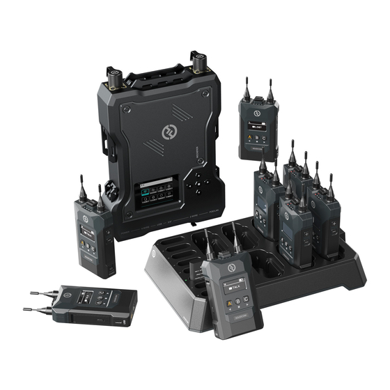
PACKING LIST ① ② ③ ④ ⑤ ⑥ ⑦ ⑧ ⑨ ⑩ ⑪ ⑫... - Page 5 PACKING LIST ① Station ② Beltpack ③ Charging Base ④ High Gain Omnidirectional Antenna ⑤ LEMO Single-Ear Headset ⑥ POE Adapter ⑦ RJ45 to XLR Transferring Cable (5 meters) ⑧ USB-Type-A to Type-C Transferring Cable ⑨ 4Pin XLR Adapter ⑩ Battery for Beltpacks ⑪...
-
Page 6: Product Interfaces
PRODUCT INTERFACES PIN1 PIN8 PIN2 PIN7 PIN3 PIN6 PIN4 PIN5 M G R L ① ② PIN1-PIN8 PIN1-PIN8 PIN2 PIN1 PIN3 ③ ④ ⑤ ① 3.5mm Headset Interface Interface Definition: M G R L Microphone Independence: 600Ω Speaker Independence: 32Ω ②... - Page 7 PRODUCT INTERFACES ③ 4-Wire Interface Input Independence: 10KΩ PIN1: NULL PIN2: NULL PIN3: AUDIO OUT+ PIN4: AUDIO IN+ PIN5: AUDIO IN- PIN6: AUDIO OUT- PIN7: GND PIN8: GND ④ 2-Wire Interface PIN1: GND PIN2: POWER PIN3: AUDIO ⑤ POE/PWR Interface PIN1: -POWER PIN2: -POWER PIN3: +POWER...
- Page 8 PRODUCT INTERFACES ① ⑧ ② ⑦ ③ ⑨ ④ ⑤ ⑥ ⑩ ⑪ ⑫⑬ ⑭ ⑮...
- Page 9 PRODUCT INTERFACES STATION ① Antenna Interface ② Up Key ③ Left Key ④ Menu/Confirm Key (Long Press to the Menu/ Short Press to Select) ⑤ Right Key ⑥ Down Key ⑦ Power Button ⑧ 3/8 Screw Hole ⑨ Interface for NP-F Type Battery ⑩...
- Page 10 PRODUCT INTERFACES...
- Page 11 PRODUCT INTERFACES BELTPACK ① Antenna ② Mute/Talk Switch Key, Press Down for Talk, Up for Mute ③ Battery Compartment Switcher ④ USB Type-C Interface ⑤ Left Key/A Group Key (The beltpack is not grouped when the indicator light is off. The beltpack is joined Group A but unable to talk or listen when the Indicator light is white.
-
Page 12: Display Introduction
DISPLAY INTRODUCTION ① Master 7.8V HollyView ② MUTE TALK TALK TALK ③ ④ ⑤ LOST TALK TALK TALK ⑥ STATION MAIN DISPLAY INTRODUCTION ① Current Battery Voltage of Station ② Current Status of Beltpack TALK: The beltpack is able to talk while listening. MUTE: The beltpack is able to listen but unable to talk. - Page 13 DISPLAY INTRODUCTION ① ② ③ TALK ④ ⑤ BELTPACK MAIN DISPLAY ① Current Signal Strength ② Charging Notice ③ Current Battery Usage ④ Beltpack Number ⑤ Current Status TALK: Able to Talk while Listening MUTE: Able to Listen but unable to Talk LOST: Disconnected from the Station LINK: Linking to the Station...
- Page 14 GUIDE...
- Page 15 GUIDE STATION MENU INTRODUCTION Long press Menu/Confirm Key for 3 Seconds to enter the Menu, following is the menu function's Introduction. ① Select “Network” to Switch WiFi on/off, See the WiFi Password and IP Address. ② Select “Master and Slave” to Set the Station as Master Device/Slave Device.
- Page 16 GUIDE ⑥ Select “2 Wire” Entering 2 Wire Settings. 6.1 After connected to 2 Wire devices, set the corresponding wire length compensation and terminal resistor of the station. Powe on the 2 Wire devices. Meanwhile the microphone of 2 Wire devices needs to be turned off or disconnected to make sure there's no other audio transmitting in the 2 Wire connection.
- Page 17 GUIDE BELTPACK MENU INTRODUCTION Long press Menu Key for 3 seconds to enter the menu, Following is the introduction of each function. ① Connect the Beltpack to the Station by USB-A to TypeC Cable, Select “Pair”, the Beltpack can Paired with Station. Select the usable number from 1 to 8 to confirm paring, Both the station and the beltpack's screens will display “Pairing…”.
- Page 18 GUIDE SET THE STATION BY WEB SERVER Power on the station. Connect POE or PWR Interface to the Ethernet interface of computer by Ethernet Cable. Configure the network segment of the computer to be consistent with the station, Then open the browser on the computer and enter the following address (Check the corresponding address through the Network Menu of the station).
-
Page 19: Product Installation
PRODUCT INSTALLATION ① ② ③ ① Station Installation 1. Install the antenna according to the picture. 2. Connect the power adapter, or install NP-F type battery. 3.Press the power button to power on. - Page 20 PRODUCT INSTALLATION...
- Page 21 PRODUCT INSTALLATION ① ② ② Beltpack Installation 1.Open the battery compartment, insert the battery in the direction marked on the battery. 2.Switch the power switcher on to power on. 3.After the beltpack status changes from “LOST” to “TALK”, You can Talk Now. Press the top button will change to “MUTE”.
- Page 22 PRODUCT INSTALLATION ④ Cascade Two Sets of Devices 1.Through the dedicated-level Ethernet cable in the accessories, Two Sets of stations can be cascaded, and the number of beltpacks can be expanded up to 16 Beltpacks. When Cascading, One of the Master Device beeds to set as Slave Device.
- Page 23 PARAMETERS Station Beltpack POE Interface (RJ45) 3.5mm Headset Interface Power Supply Interface (RJ45) LEMO Headset Interface 4 Wire Audio Interface USB-Type-C Interface Interfaces USB Interface 2 Wire Audio Interface USB Type-C Interface POE Power Supply Power Supply 1500mAh Lithium Polymer Battery NP-F Type Battery Frequency Response 200Hz to 7KHz...
- Page 24 SUPPORT If encounter any problems in using the product or need any help,please follow these ways to get more technical support: support@hollyland-tech.com...
- Page 25 support@hollyland-tech.com...
Need help?
Do you have a question about the SOLIDCOM M1 and is the answer not in the manual?
Questions and answers