Table of Contents
Advertisement
Quick Links
Advertisement
Table of Contents

Related Manuals for Keysight Technologies Z Series


Summary of Contents for Keysight Technologies Z Series
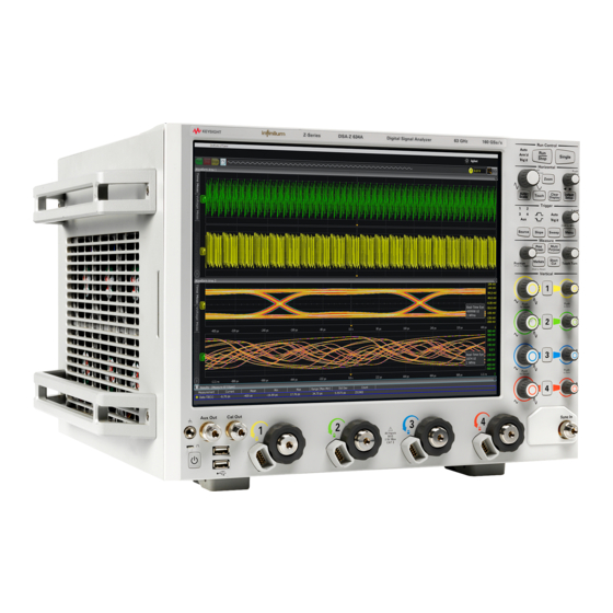
- Page 1 Keysight Infiniium Z-Series Oscilloscopes User’s Guide...
- Page 2 Notices Manual Part Number © Keysight Technologies, Inc. 2014 1987) or any equivalent agency regulation or contract clause. Use, duplication or disclo- No part of this manual may be reproduced in 54932-97004 sure of Software is subject to Keysight Tech- any form or by any means (including elec- nologies’...
-
Page 3: Infiniium Z-Series Oscilloscopes-At A Glance
Infiniium Z-Series Oscilloscopes—At a Glance Table 1 Z-Series Oscilloscope Bandwidths, Sample Rates, and Memory Depths Band wid th Sample rate Memory depth 2 channel 4 channel 2 channel 4 channel Standard Maximum DSAZ634A 63 GHz 33 GHz 160 GS/s 80 GS/s 50 Mpts 2 Gpts DSOZ634A... - Page 4 Ease of use with high performance The Infiniium Z-Series oscilloscopes combine unprecedented ease of use with high-performance digitizing oscilloscope functionality to simplify your design and analysis measurement tasks. • Traditional oscilloscope front-panel interface provides direct access to the controls needed for most troubleshooting tasks. •...
- Page 5 • Use auxiliary trigger to increase triggering flexibility. Vertical controls set attenuation and position • Color-coded knobs make it easy to find the controls that affect each waveform. Marker and quick measurements help measure waveform parameters • Use waveform markers 1 and 2 to check voltage or -time at any point on the Δ...
-
Page 6: In This Guide
In This Guide This guide provides the information you need to begin using the Infiniium Z-Series oscilloscopes. Chapter 1, “Setting Up the Oscilloscope,” starting on page 11 includes power and air flow requirements, plus other setup information. Chapter 2, “Using the Oscilloscope,” starting on page 25 gives an overview of the front and back panel inputs and outputs, front-panel controls, and user interface, and tells you how to perform basic operations with the oscilloscope. -
Page 7: Table Of Contents
Contents Infiniium Z-Series Oscilloscopes—At a Glance In This Guide 1 Setting Up the Oscilloscope Inspecting Package Contents Environmental Characteristics Positioning for Proper Airflow Connecting a Mouse, Keyboard, and LAN Cable Connecting Power Use Supplied Power Cord Properly Ground the Oscilloscope Power Supply Protection Features Connecting Oscilloscope Probes Maximum Input Voltage... - Page 8 RealEdge 1R, 3R Channel Inputs Ground Aux Out Cal Out Probe Compensation Terminal USB Host Ports Front or Back Panel Inputs and Outputs Trig Out Aux Trig Back Panel Inputs and Outputs Motherboard I/O 10 MHz In, 10 MHz Out 100 MHz In, 100 MHz Out Front Panel Controls (Keys and Knobs) Overview User Interface Overview...
- Page 9 3 Online Help and Other Information Accessing the Online Help Navigating the Online Help Using the Demo Wizard A Safety Information English French B Working in Comfort About Repetitive Strain Injury What is RSI? What causes RSI? What if I experience discomfort? Mice and Other Input Devices Index Infiniium Z-Series Oscilloscopes User’s Guide...
- Page 10 Infiniium Z-Series Oscilloscopes User’s Guide...
-
Page 11: Setting Up The Oscilloscope
Agilent Infiniium Z-Series Oscilloscopes User’s Guide 1 Setting Up the Oscilloscope Inspecting Package Contents Environmental Characteristics Positioning for Proper Airflow Connecting a Mouse, Keyboard, and LAN Cable Connecting Power Connecting Oscilloscope Probes Connecting Threaded RF Cables Tilting the Oscilloscope for Easier Viewing Turning On the Oscilloscope Verifying Basic Oscilloscope Operation Installing Application Programs on Infiniium... -
Page 12: Inspecting Package Contents
• If the shipping container is damaged, or the cushioning materials show signs of stress, notify the carrier and your Keysight Technologies Sales Office. Keep the shipping materials for the carrier’s inspection. The Keysight Technologies Sales Office will arrange for repair or replacement at Keysight’s option without waiting for claim settlement. -
Page 13: Environmental Characteristics
Setting Up the Oscilloscope Environmental Characteristics Table 2 Z-Series Oscilloscope Environmental Characteristics Environment Indoor use only. Ambient Temperature Operating: 5 °C to + 40 °C Non-operating: –40°C to +65 °C Humidity Operating: up to 95% relative humidity (non-condensing) at +40 °C Non-operating: up to 90% relative humidity at +65 °C Altitude Operating: up to 4,000 meters (12,000 feet) -
Page 14: Positioning For Proper Airflow
Setting Up the Oscilloscope Positioning for Proper Airflow Position the oscilloscope where it will have sufficient clearance for airflow around the back and sides. If you plan to connect multiple Infiniium oscilloscopes together, refer to the Keysight MultiScope Hardware Configuration Guide for airflow requirements. Top: Minimum 0 mm Front panel of oscilloscope... -
Page 15: Connecting A Mouse, Keyboard, And Lan Cable
Setting Up the Oscilloscope Connecting a Mouse, Keyboard, and LAN Cable A mouse and keyboard can be plugged into the USB host ports. Four host ports are on the rear panel, with two more on the front panel. Connect your LAN cable to the RJ-45 connector on the back panel of the oscilloscope. -
Page 16: Connecting Power
Setting Up the Oscilloscope Connecting Power Table 3 Power Requirements Power 100 - 240 VAC ±10% at 50/60 Hz Maximum input power: 1350 Watts Well-regulated power is required for 100-120 VAC operation Connect the power cord to the rear of the oscilloscope, then to a suitable AC voltage source. -
Page 17: Power Supply Protection Features
Setting Up the Oscilloscope Power Supply Protection Features The Z-Series oscilloscope’s power supply has built-in protection features for over-voltage, over-current, and over-temperature fault conditions. Figure 2 identifies the power supply LEDs and Table 4 describes their conditions. Table 4 Power Supply LED Meanings AC LED DC/FLT (Faul t) LED Cond ition... - Page 18 Setting Up the Oscilloscope Figure 3 Z-Series Oscilloscope Probe Connectors The AutoProbe II interface works with the InfiniiMax III probing system. There are four different InfiniiMax III probe amplifiers ranging from 16 to 30 GHz. For more information, see Keysight InfiniiMax III Probing System Data Sheet.
-
Page 19: Connecting Threaded Rf Cables
Setting Up the Oscilloscope Connecting Threaded RF Cables You can connect threaded RF cables to the Infiniium Z-Series oscilloscope inputs. For input channels 1 through 4, you can connect 3.5 mm threaded RF cables using the automatic torque “clutch” mechanism to ensure a consistent 8 in.-lbs. connection. -
Page 20: Turning On The Oscilloscope
Setting Up the Oscilloscope Turning On the Oscilloscope Press the power switch in the lower left corner of the oscilloscope front panel. Z-Series Z-Series DSO-Z 204A DSO-Z 204A Digital Storage Oscilloscope Digital Storage Oscilloscope 20 GHz 20 GHz 80 GSa/s 80 GSa/s Digital Storage Oscilloscope DSO-X 96204Q... -
Page 21: Verifying Basic Oscilloscope Operation
Setting Up the Oscilloscope Verifying Basic Oscilloscope Operation Install the supplied connector savers to each channel input. Keysight recommends using the connector savers to protect the input connectors. Connect one end of the 54916-61626 calibration cable to oscilloscope input channel 1. Connect the other end of the calibration cable to the Cal Out connector on the front panel. -
Page 22: Installing Application Programs On Infiniium
Setting Up the Oscilloscope If you do not see the waveform, make sure your power source is adequate, the oscilloscope is properly powered on, and the cable is connected securely to the channel input and to the calibration output. Move the mouse around the mouse surface and verify that the on-screen pointer follows the mouse movement. -
Page 23: Changing Windows Operating System Settings
Setting Up the Oscilloscope Changing Windows Operating System Settings Exit the oscilloscope application before changing any Windows operating system settings NOTE outside of the oscilloscope application. Many Windows operating system settings can be changed to suit your own personal preferences. However, some operating system settings should not be changed because doing so would interfere with the proper operation of the oscilloscope. -
Page 24: Turning Off The Oscilloscope
Setting Up the Oscilloscope Turning Off the Oscilloscope Press the power switch at the lower left corner of the oscilloscope front panel. The oscilloscope will go through a normal Windows operating system shutdown process. Cleaning the Oscilloscope Clean the oscilloscope with a soft cloth dampened with a mild soap and water solution. -
Page 25: Using The Oscilloscope
Keysight Infiniium Z-Series Oscilloscopes User’s Guide 2 Using the Oscilloscope Front Panel Inputs and Outputs Back Panel Inputs and Outputs Front Panel Controls (Keys and Knobs) Overview User Interface Overview Menu Overview Using the Setup and Display Controls Starting and Stopping Waveform Acquisitions Adjusting the Horizontal Time Scale and Trigger Position Adjusting the Vertical Settings Setting Up Triggers... -
Page 26: Front Panel Inputs And Outputs
Using the Oscilloscope Front Panel Inputs and Outputs On the Infiniium Z-Series oscilloscopes, the channel inputs and the Aux Out and Cal Out outputs appear on the lower part of the front panel. The ground plug, probe compensation terminal, and two USB host ports are also located here. Aux Out Cal Out RealEdge... -
Page 27: Ground
Using the Oscilloscope When enabled, the RealEdge 1R and 3R channel inputs take over the standard channels 1-4, except for the trigger circuitry on channels 2 and 4. When RealEdge is enabled, you can still trigger on signals connected to the channel 2 and 4 inputs (but you cannot capture or display data from these signals). -
Page 28: Front Or Back Panel Inputs And Outputs
Using the Oscilloscope Front or Back Panel Inputs and Outputs Trig Out and Aux Trig appear on the back panel in 50 GHz and 63 GHz bandwidth models of Z-Series oscilloscopes, and on models that have the optional sync port. They appear on the front panel in 20 GHz, 25 GHz, and 33 GHz bandwidth models. -
Page 29: Back Panel Inputs And Outputs
Using the Oscilloscope Back Panel Inputs and Outputs The Infiniium Z-Series oscilloscope’s back panel has the motherboard I/O connectors and reference clock synchronization connectors. External monitor LAN connector connector CAUTION: Power down Removable instrument before insertion or removal Hard Drive of hard drive. -
Page 30: 100 Mhz In, 100 Mhz Out
Using the Oscilloscope • Amplitude: 178 mV peak to 1 V peak • Frequency: 10 MHz ±5 ppm high-quality sine wave or square wave To use a 10 MHz external reference clock, connect the external clock to the 10 MHz In BNC connector; then, in the Infiniium oscilloscope application's Horizontal Setup dialog box (Setup >... -
Page 31: Front Panel Controls (Keys And Knobs) Overview
Using the Oscilloscope Front Panel Controls (Keys and Knobs) Overview The Infiniium Z-Series oscilloscope front panel gives you direct access to the functions needed to perform the most common measurements, using a traditional oscilloscope interface. Knobs and keys let you directly set vertical and horizontal parameters. -
Page 32: User Interface Overview
Using the Oscilloscope User Interface Overview With the user interface for the Infiniium oscilloscope, you can access all the configuration and measurement features of the oscilloscope through an easy-to-use system of windows, menus, toolbars, dialog boxes, icons, wizards, and buttons. The user interface is arranged so the most common functions affecting the waveform display are located around the edge of the waveform display area. - Page 33 Using the Oscilloscope Scale settings Drag & Drop measurements Ground reference indicator Figure 12 Infiniium Oscilloscope Waveform Display Area The waveform display area shows up to eight waveform areas. Several display options are available, such as grids or horizontal and vertical scales. Avoid Overdriving Vertical Input Amplifiers NOTE When zooming on a waveform with the oscilloscope running, be careful to keep the signal...
- Page 34 Using the Oscilloscope Expand drag & drop Pin/unpin Zoom on/off measurements controls Set horizontal Markers turn on/ position set up Set horizontal scale Access the Horizontal Setup dialog box Figure 13 Infiniium Oscilloscope Bottom of Display A Results pane is visible at the very bottom of the display when you do something that requires it, such as take a measurement.
-
Page 35: Menu Overview
Using the Oscilloscope Menu Overview You can use menus to perform defined operations, set up measurement parameters, and access every function the oscilloscope provides. Infiniium Z-Series Oscilloscopes User’s Guide... - Page 36 Using the Oscilloscope Figure 15 Infiniium Oscilloscope Menus Look through the menus to get an overview of the many features and capabilities of your Infiniium oscilloscope. Infiniium Z-Series Oscilloscopes User’s Guide...
-
Page 37: Using The Setup And Display Controls
Using the Oscilloscope Using the Setup and Display Controls You can set the oscilloscope to a known starting condition and set the display to suit your preferences. Auto Clear Default Touch Scale Display Setup Figure 16 Setup and Display Control Keys •... -
Page 38: Starting And Stopping Waveform Acquisitions
Using the Oscilloscope Starting and Stopping Waveform Acquisitions Use the acquisition run controls to run and stop acquisitions or make a single acquisition. The boxed area of the memory bar above the waveform display area shows how much of acquisition memory is displayed on the screen. Run and Stop waveform acquisition... -
Page 39: Adjusting The Horizontal Time Scale And Trigger Position
Using the Oscilloscope Adjusting the Horizontal Time Scale and Trigger Position Use the horizontal controls to configure the oscilloscope’s horizontal scale (time per division) and horizontal position of the waveform. You can view a magnified section of the waveform using the zoom window. Use gestures on the touch screen to adjust the waveform horizontal scale and position. -
Page 40: Adjusting The Horizontal Scale
Using the Oscilloscope Ad justing the horizontal scale The horizontal scale knob is the larger of the two horizontal control knobs, marked with a set of sine wave symbols. • To stretch the waveform horizontally, turn the horizontal scale knob clockwise. To shrink it horizontally, turn the knob counter-clockwise. -
Page 41: Setting The Scale, Position, And Timebase Reference
Using the Oscilloscope The horizontal scale and horizontal position controls now change how the waveform is shown in the zoomed timebase window. The horizontal scale will change the amount of magnification, while the position will change the part of the waveform in the main window that is shown in the zoomed window. •... -
Page 42: Adjusting The Vertical Settings
Using the Oscilloscope Adjusting the Vertical Settings Use the vertical controls to set the vertical scaling (volts per division) and vertical offset. You can also turn the display on or off for a particular channel. Use this key to turn analog channel 1 on or off Vertical... -
Page 43: Turning A Channel On Or Off
Using the Oscilloscope Turning a channel on or off • To turn channels 1 through 4 on or off, press the channel number key on the front panel or click the Additional Signals button in the toolbar. When you turn off a channel, the current vertical scale and offset fields for that channel disappear. - Page 44 Using the Oscilloscope For Keysight Technologies probes that are compatible with AutoProbe II interfaces, the oscilloscope will automatically set these characteristics (except for skew) after identifying the probe when it is connected to the channel input. Infiniium Z-Series Oscilloscopes User’s Guide...
-
Page 45: Setting Up Triggers
Using the Oscilloscope Setting Up Triggers Use the trigger controls to set the conditions on which the oscilloscope will trigger and acquire an input signal. You can set up a variety of trigger conditions. Edge triggers and the parameters for edge triggering can be set up from the front panel. Trigger configuration settings you make using the user interface are reflected in the front-panel status indicators, and will remain set unless you change them or press the [Default Setup] key. - Page 46 Using the Oscilloscope When Trig’d is selected, the oscilloscope must find the trigger before capturing and displaying data. When Auto is selected, if a trigger does not occur within a certain amount of time, an acquisition is automatically saved and displayed. In Auto trigger mode, you are able to see your signals while setting up the desired trigger.
-
Page 47: Using Markers And Making A Measurement
Using the Oscilloscope Using Markers and Making a Measurement With the measurement controls you can display and adjust markers, define a key to perform automatic measurements or other quick actions, and make measurements. Press to perform configured action (like Quick Meas) Measure Print Multi... -
Page 48: Making A Measurement On A Waveform
Using the Oscilloscope Making a measurement on a waveform Click and drag a measurement icon to the waveform event you want to measure, or click a measurement icon and specify which source you want to measure in the dialog box that appears. For measurements on waveform features, such as those that involve waveform edges, if you click the measurement icon and specify a source, the measurement defaults to using the feature closest to the horizontal reference point. -
Page 49: Using Markers
Using the Oscilloscope The 10 preset measurements defined in the Quick Measurement configuration are enabled and results are displayed on the screen for the first waveform source. • To measure parameters for another waveform, press the [Multi Purpose] key until that waveform is the one shown in the measurement readout. Continuing to press the [Multi Purpose] key cycles through each of the waveforms available. - Page 50 Using the Oscilloscope Dragging a marker makes it easy to quickly move the marker to the desired waveform event. You can use the front-panel Position knob for fine adjustment, or click Measure > Markers... and set the marker position precisely. Infiniium Z-Series Oscilloscopes User’s Guide...
-
Page 51: Saving And Printing Data
Using the Oscilloscope Saving and Printing Data • Click File > Save > to save your composite, setup, waveform, screen image, or measurement data. • Click File > Copy Screen Image to easily copy and paste a screen image into a document. -
Page 52: Forcing A Default Setup
Using the Oscilloscope Forcing a Default Setup If your Infiniium oscilloscope is not working properly when you start it up, follow these steps to perform a default setup and return the Infiniium to normal operation. Click Control > Default Setup or press the [Default Setup] key. If the oscilloscope is still not working properly, click Control >... -
Page 53: Online Help And Other Information
Keysight Infiniium Z-Series Oscilloscopes User’s Guide 3 Online Help and Other Information Accessing the Online Help Navigating the Online Help Using the Demo Wizard Most of the information about using the Infiniium oscilloscope effectively is included in the online help. The online help is accessible from the menu bar and by clicking the question mark in the top right corner of dialog boxes. - Page 54 Online Help and Other Information Figure 28 Online Help Home Page Viewing the Online Help Window NOTE The online help window always stays on top of the interface display, so you can refer to it while working with the oscilloscope. You can move the window around the screen or resize it to make it easier to use.
-
Page 55: Navigating The Online Help
Online Help and Other Information • For information about items in a dialog box, click the Help button in that dialog box. Figure 29 Help Button for Dialog Box Help Navigating the Online Help The online help provides several ways to find the information you need. Use the Contents tab to browse topics in the help system by clicking topics in the left pane. - Page 56 Online Help and Other Information Figure 30 FFT Demo Infiniium Z-Series Oscilloscopes User’s Guide...
-
Page 57: A Safety Information
Failure to comply with these precautions or with specific warnings or operating instructions in the product manuals violates safety standards of design, manufacture, and intended use of the instrument. Keysight Technologies assumes no liability for the customer's failure to comply with these requirements. Product manuals are provided with your instrument on CD-ROM and/or in printed form. - Page 58 Safety Information Do Not Mod ify the Do not install substitute parts or perform any unauthorized modification to the product. Instrument Return the product to an Keysight Sales and Service Office for service and repair to ensure that safety features are maintained. In Case of Damage Instruments that appear damaged or defective should be made inoperative and secured against unintended operation until they can be repaired by qualified service personnel.
- Page 59 Safety Information Safety Symbols Table 5 Description of Safety related symbols that may appear on a product (Sheet 1 of 2) Symbol Description Direct current Alternating current Both direct and alternating current Three phase alternating current Earth ground terminal Protective earth ground terminal Frame or chassis ground terminal Terminal is at earth potential Equipotentiality...
- Page 60 Safety Information Table 5 Description of Safety related symbols that may appear on a product (Sheet 2 of 2) Symbol Description Caution, refer to accompanying documentation Caution, risk of electric shock Do not apply around or remove from HAZARDOUS LIVE conductors Application around and removal from HAZARDOUS LIVE conductors is permitted Caution, hot surface Ionizing radiation...
-
Page 61: French
à la conception, à la fabrication et à l'usage normal de l'instrument. Keysight Technologies ne saurait être tenu responsable du non-respect de ces consignes. Les manuels des produits sont fournis avec votre instrument sur CD-ROM et/ou en version papier. - Page 62 Safety Information La mention ATTENTION indique un risque. Si la manoeuvre ou le procédé correspondant CAUTION n'est pas exécuté correctement, il peut y avoir un risque de dommages à l'appareil ou de perte de données importantes. En présence de la mention ATTENTION, il convient de s'interrompre tant que les conditions indiquées n'ont pas été...
- Page 63 Safety Information Table 6 Description des Symboles de Sécurité qui pourraient apparaître sur le produit. (Sheet 2 of 2) Symboles Description Alimentation à l'arrêt. Alimentation en mode veille. Lorsque l'interrupteur est en mode veille, l'unité n'est pas complètement déconnectée de l'alimentation secteur. Position Marche d'un interrupteur par bouton poussoir bi-stable.
- Page 64 Safety Information Infiniium Z-Series Oscilloscopes User’s Guide...
-
Page 65: B Working In Comfort
Keysight Infiniium Z-Series Oscilloscopes User’s Guide B Working in Comfort About Repetitive Strain Injury Mice and Other Input Devices To optimize your comfort and productivity, it is important that you set up your work area correctly and use your Infiniium oscilloscope properly. With that in mind, we have developed some setup and use recommendations for you to follow based on established ergonomic principles. -
Page 66: About Repetitive Strain Injury
Working in Comfort About Repetitive Strain Injury Because your comfort and safety are our primary concern, we strongly recommend that you use the Infiniium oscilloscope in accordance with established ergonomic principles and recommendations. Scientific literature suggests that there may be a relationship between injury to soft tissues—especially in the hands and arms—and prolonged improper use of keyboards or other equipment requiring repeated motions of the hands and forearms. -
Page 67: Mice And Other Input Devices
Working in Comfort Mice and Other Input Devices Various aspects of using mice and other input devices may increase your risk of discomfort or injury. Observing the following recommendations may reduce that risk. • Try to keep your hand, wrist, and forearm in a neutral position while using your mouse or other input device. - Page 68 Working in Comfort Infiniium Z-Series Oscilloscopes User’s Guide...
-
Page 69: Index
Index connecting horizontal position LAN card, in zoom mode, power, accessing probes, index, contents online help, online help, accessories icons contents topic, and options, measurement, customizing display layout, acquisition increasing display update rate, cycling starting and stopping, index markers through channels, adjusting accessing, analog channel’s vertical offset,... - Page 70 Index level online help RSI, trigger, accessing, using the mouse, line voltage, index, Run key, navigating, overview, windows, opening the online help, magnifying safety, options a section of the waveform, scaling and accessories, main timebase, adjusting analog channel’s vertical, making seconds per division oscilloscope measurements,...
- Page 71 Index user interface, front panel, use of color, using markers, oscilloscope, verifying basic operation, vertical inputs overdriving, vertical offset adjusting analog channels, vertical scaling adjusting analog channels, volts per division adjusting, waveform magnifying, waveform features measurements on, moving markers to, waveforms acquiring, associating with measurement...
- Page 72 Index Infiniium Z-Series Oscilloscopes User’s Guide...
Need help?
Do you have a question about the Z Series and is the answer not in the manual?
Questions and answers