Table of Contents
Advertisement
Quick Links
Advertisement
Table of Contents
Troubleshooting

Related Manuals for Keysight Technologies Z5623A Option H01


Summary of Contents for Keysight Technologies Z5623A Option H01
- Page 1 Keysight Technologies Z5623A Option H01 User's Guide...
- Page 2 THESE TERMS, THE WARRANTY Keysight shall be under no obligation TERMS IN THE SEPARATE to update, revise or otherwise modify © Keysight Technologies, Inc. AGREEMENT WILL CONTROL. the Software. With respect to any 2002-2014, 2017, 2017 technical data as defined by FAR Technology Licenses 2.101, pursuant to FAR 12.211 and...
-
Page 3: Table Of Contents
Table of Contents Z5623A Option H01 Introduction ............. . 2 Description . - Page 4 Table of Contents Safety and Information ..........28 Introduction.
- Page 5 Z5623A Option H01 Keysight Z5623A-H01 User's Guide...
-
Page 6: Introduction
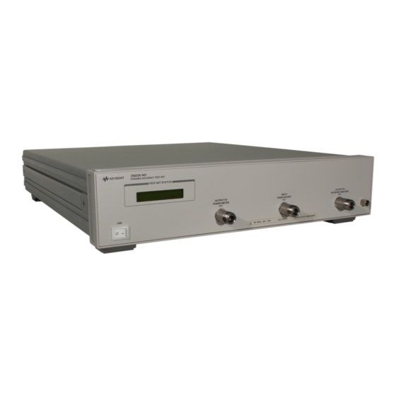
Z5623A Option H01 Introduction Introduction This document describes how to use and service the Z5623A Option H01 Dynamic Accuracy Test Set. Figure 1 Z5623A-H01 Dynamic Accuracy Test Set Keysight Z5623A-H01 User's Guide... -
Page 7: Description
Z5623A Option H01 Description Description The Z5623A Option H01 Dynamic Accuracy Test Set is designed for use with the PNA and PNA-X Series Network Analyzers. The Z5623A H01 can measure a receiver's relative power linearity (dynamic accuracy) when used with an E-Series power meter, a thermocouple power sensor, and a test algorithm. The Z5623A H01 was designed for maximum measurement accuracy over a 120 dB dynamic range. -
Page 8: General Specifications
A functional certificate is supplied for the Z5623A Option H01. The Z5623A Option H01 performance is based on external components such as the calibration kit and network analyzer. There are no internal adjustment in the Z5623A Option H01, therefore an annual calibration is not required. -
Page 9: Electrical And Environmental Requirements
Air conditioning capacity must be consistent with the rating listed in the PNA and PNA-X standard documentation. Dimensions and Space Requirements Standard installation of the Z5623A Option H01 and PNA includes configuration and installation on a customer provided lab bench or table top of adequate size and strength. Table 2... - Page 10 Z5623A Option H01 Electrical and Environmental Requirements Ventilation Requirements: When installing the instrument in a cabinet, the convection into and out of the instrument must not be restricted. The ambient temperature (outside the cabinet) must be less than the maximum operating temperature of the instrument by 4 °C for every 100 watts dissipated in the...
- Page 11 Israel 200 (78) Jade Gray 8120-5181 a. E =earth ground, L = line, and N = neutral. b. Plug identifier numbers describe the plug only. The Keysight Technologies part number is for the complete cable assembly. Keysight Z5623A-H01 User's Guide...
-
Page 12: Required Conditions For Accuracy-Enhanced Measurement
Z5623A Option H01 Electrical and Environmental Requirements Required Cond itions for Accuracy Enhanced Measurement Accuracy–enhanced (error–corrected) measurements require the ambient temperature of the PNA and Test Set to be maintained within ±1 °C of the ambient temperature at calibration. Table 3... -
Page 13: Front And Rear Panel Features
Z5623A Option H01 Front and Rear Panel Features Front and Rear Panel Features Refer to the standard instrument documentation for damage limits to the ports. Verify that your test setup will not cause those limits to be exceeded. Front Panel... -
Page 14: Rear Panel
Z5623A Option H01 Front and Rear Panel Features Rear Panel Figure 5 Rear Panel Parallel In/Out Ports GPIB Connector Address Switch Line Module (Non-Functional) GPIB Connector This connector allows the test set to be connected directly to a controller. Address Switch The address switch sets the GPIB address of the test set. -
Page 15: Available Fuses
Z5623A Option H01 Front and Rear Panel Features Available Fuses • Fuse (115 V orientation) (F 3A/250V, 2110-0780) Figure 6 Line Fuse Verify that the premise electrical voltage supply is within the range specified on the instrument. Keysight Z5623A-H01 User's Guide... -
Page 16: System Setup
Z5623A Option H01 System Setup System Setup The Z5623A Option H01 Test Set is designed to be placed near the network analyzer on a bench top and connected as shown in Figure 1. Connect a GPIB cable from the controller to the rear panel of the network analyzer. See “Operation”... -
Page 17: Setting The Test Set Address Switch
Z5623A Option H01 System Setup Setting the Test Set Address Switch The test set is shipped with the GPIB address set to 12, as shown in Figure To set the GPIB address, set all five switches so that the sum of the switches in the “ON” (or 1) position equals the desired address. -
Page 18: Operation
Z5623A Option H01 Operation Operation The Z5623A Option H01 is a “slave” instrument: a controller must be used to control the test set. The controller can control the test set using GPIB commands via the GPIB connector. Commands The only way to control the test set is to address the Option H01 test set directly over GPIB using a controller to write directly to the test set's GPIB port. - Page 19 Z5623A Option H01 Operation Table 4 Test Port Addresses Connection Path GPIB Command Attenuator A = 0 dB at_a = 0 Attenuator A = 1 dB at_a = 1 Attenuator A = 2 dB at_a = 2 Attenuator A = 3 dB...
- Page 20 Z5623A Option H01 Operation Table 4 Test Port Addresses (Continued) Connection Path GPIB Command Filter IN f_in Filter OUT f_out Isolator IN i_in Isolator OUT i_out Standard Configuration standard Modified Configuration modified Keysight Z5623A-H01 User's Guide...
-
Page 21: Reset Command
Z5623A Option H01 Operation To identify the test set serial number, send the following commands: OUTPUT 712;"sn?" ENTER 712;Sn$ DISP Sn$ The "idn?" command displays the instrument IP on the front panel; it does not respond over the GPIB. Reset Command When the Reset command is sent, the test set is set to the default state where the attenuators are set to 0 dB and the amplifier is switched out. -
Page 22: Service Information
The use of adapters may be required and their effects should be accounted within the measurements. Prior to June 2007, the Z5623A Option H01 had hard specifications, therefore a calibration certificate was available for the test set. The specifications have now been replaced with typical performance characteristics. -
Page 23: Test Instructions
Z5623A Option H01 Service Information Test Instructions A Test Record sheet on page 20, Table 6, is provided to record your 'Measured Results' and confirm they meet the typical values shown. 1. Power Meter Path Insertion Loss, without Amplifier: (S21) a. -
Page 24: Test Record Sheet
Z5623A Option H01 Service Information Table 6 Z5623A Option H01 - Test Record Sheet Port Measured Typical Test Description Signal Path Results Results INPUT from S21 Insertion Loss SOURCE w/o Amplifier 1.2 GHz –7.5 (± 3 dB) __________ OUTPUT to ≤... -
Page 25: Functional Test Record
Z5623A Option H01 Service Information Functional Test Record The following pages are designed to be duplicated and used as a template for the performance tests. Test Facility_______________________________ Report Number__________________________ __________________________________________ __________________________________________ Date____________________________________ Date of Last System Calibration___________ ________________________________________ Tested by_________________________________... -
Page 26: Replaceable Parts
Service Information Replaceable Parts The following table contains the list of replaceable parts for the Keysight Z5623A Option H01 Dynamic Accuracy Test Set. If any of these parts or assemblies are replaced, you must run all performance tests to verify conformance to specifications. - Page 27 Z5623A Option H01 Service Information Table 7 Replaceable Parts (Continued) RF Cable NA PT8496 Z5623-20006 RF Cable WS-4/A IN Z5623-20007 RF Cable SW-1/AMOUT Z5623-20008 RF Cable Semi-rigid Z5623-20681 RF Cable Semi-rigid Z5623-20682 RF Cable Semi-rigid Z5623-20683 RF Cable Semi-rigid Z5623-20684...
-
Page 28: Troubleshooting
Refer to Figure 10, “Z5623A Option H01 Standard Block Diagram,” an aid in troubleshooting. The theory of operation information can be found beginning on page Al ways turn the instrument power off before removing or installing an assembly. -
Page 29: Troubleshooting The Switches And Switch Driver Board
If the voltages are not correct, replace the Attn/Switch driver board. Refer to Figure 10 for a block diagram of the major components wiring interconnects and the switching paths of the Keysight Z5623A Option H01. Figure 10 Z5623A Option H01 Standard Block Diagram Keysight Z5623A-H01 User's Guide... -
Page 30: Theory Of Operation
Figure 11 Simplified Block Diagram The Z5623A Option H01 was designed to allow a power meter to be used as the linearity reference. The power splitter and attenuators AT_a and AT_b are used in conjunction to vary the power to the receiver by 120 dB while the power delivered to the power meter stays within a 10 dB range. -
Page 31: Power Supply Theory
Z5623A Option H01 Theory of Operation It is necessary to eliminate the step size error and the mismatch error between the receiver and the test set whenever AT_b switches. This is done using an attenuator correction measurement embedded into the measurement algorithm. The source power of the network analyzer is adjusted until the receiver reads the same power before and after the attenuators are changed. -
Page 32: Safety And Information
Z5623A Option H01 Safety and Information Safety and Information Introduction Review this product and related documentation to familiarize yourself with safety markings and instructions before you operate the instrument. This product has been designed and tested in accordance with accepted industry standards, and has been supplied in a safe condition. -
Page 33: Before Applying Power
Z5623A Option H01 Safety and Information Before Applying Power Verify that the premises electrical supply is within the range of the instrument. The instrument has an autoranging power supply. If this prod uct is not used as specified, the protection provided by the equipment could be impaired. -
Page 34: Connector Care And Cleaning Precautions
Z5623A Option H01 Safety and Information Danger of explosion if battery is incorrectly replaced. Replace only with the same or equivalent type recommended. Discard used batteries accord ing to manufacturer’s instructions. For continued protection against fire hazard replace line fuse only with same type and rating. -
Page 35: Regulatory Information
Z5623A Option H01 Regulatory Information Regulatory Information Listed below are definitions of the markings that may be found on the product. Instrument Markings The instruction documentation symbol. The product is marked with this symbol when it is necessary for the user to refer to the instructions in the documentation. -
Page 36: Emc Compliance
Z5623A Option H01 Regulatory Information EMC Compliance Complies with the essential requirements of the European EMC Directive as well as current editions of the following standards (dates and editions are cited in Declarations of Conformity): • IEC/EN 61326-1 • CISPR Pub 11 Group 1, Class A •... -
Page 37: Keysight Support, Services, And Assistance
Keysight for repair. If you wish to send your instrument to Keysight Technologies for service or repair: • Include a complete description of the service requested or of the failure and a description of any failed test and any error message. - Page 38 This information is subject to change without notice. © Keysight Technologies 2002-2014, 2017 Edition 1, September 2017 Supersedes: June 2017 Z5623-90001 www.keysight.com...
Need help?
Do you have a question about the Z5623A Option H01 and is the answer not in the manual?
Questions and answers