Advertisement
Quick Links
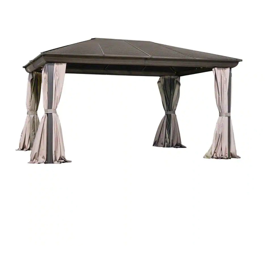
43226MR-22
BROWN
43226MR-32
SLATE
METAL ROOF 12'x16' GAZEBO
ASSEMBLY INSTRUCTIONS
DO NOT DESTROY THE BOXES UNTIL COMPLETELY ASSEMBLED
FOR FUTURE REFERENCE,
TAKE PICTURES OF ALL SIX SIDES OF EACH OF THE BOXES UPON RECEIPT.
PLEASE VERIFY THE CONTENT OF EACH BOX AGAINST THE LIST OF PARTS
Assembly With Two Or More Adults Recommended
Base Dimensions 10' 11" x 15'6"
APPROX.
Largest Dimensions 11' 11" x 16'2"
Overall Height 108.5''
ZZZ-205.43226MR.0705-21.GP.EN.doc
WEB VERSION
1
Advertisement

Related Manuals for Gazebo penguin 43226MR-22


Summary of Contents for Gazebo penguin 43226MR-22
- Page 1 43226MR-22 BROWN 43226MR-32 SLATE METAL ROOF 12’x16’ GAZEBO ASSEMBLY INSTRUCTIONS DO NOT DESTROY THE BOXES UNTIL COMPLETELY ASSEMBLED FOR FUTURE REFERENCE, TAKE PICTURES OF ALL SIX SIDES OF EACH OF THE BOXES UPON RECEIPT. PLEASE VERIFY THE CONTENT OF EACH BOX AGAINST THE LIST OF PARTS Assembly With Two Or More Adults Recommended Base Dimensions 10’...
- Page 2 Some jurisdictions may require permits for, or otherwise regulate, installation and use. For assistance with assembly, installation, parts, or customer service, contact Gazebo Penguin Customer Service Department at the numbers listed below (English & French, Mon-Fri 8:00 AM to 4:00 PM EST):...
- Page 3 3. Leaking due to heavy rain may happen, please refer to the instruction manual for window positions and information on how to evacuate the water. 4. The product is only warranted in the event it is installed in accordance with the Gazebo Penguin’s written instructions enclosed with the product.
- Page 4 43226MR GAZEBO BROWN (see page 8 for Slate parts) PACKED PACKED PART DIAGRAM PART DIAGRAM IN BOX IN BOX (20-042-22) (11-626-22) 85 ½ ” 65 ½” TOP LEFT CENTRAL BEAM (20-039-22) (11-627-22) 92 5/8” 65 ½” ROOF TOP RIGHT BEAM RAFTER (11-688-22) (20-014-22)
- Page 5 PACKED PACKED PART DIAGRAM PART DIAGRAM IN BOX IN BOX (20-060-22) (20-032-22) SOLIDIFYING SOLIDIFYING BRACKET (20-070-22) (20-034-22) 55 ¼” SOLIDIFYING RIGHT FLASHING (17-053-22) (20-035-22) FINISHING SOLIDIFYING (19-097-22) (12-030-22) CORNER MOUNTING BRACKET BRACKET (20-012-22) (20-071-22) 55 ¼” 60 3/8” LEFT COVER FLASHING ROOF BAR (20-040-22)
- Page 6 PACKED PACKED PART DIAGRAM PART DIAGRAM IN BOX IN BOX (20-0230-22) (20-023-22 ) RIGHT UPPER LEFT LOWER ROOF PANEL ROOFPANEL, 12’ SIDE 16’ SIDE (08-158-22) (20-024-22) BOLT RIGHT LOWER (M6x16mm) ROOF PANEL, 16’ SIDE (08-156-22) SCREW (M4x16mm) (20-025-22) (08-167-22) LEFT LOWER SCREW ROOF PANEL, (M6x63.5mm)
- Page 7 PACKED PART DIAGRAM IN BOX *NOT INCLUDED IN THE BOX (16-118-22) SCREW DESCRIPTION COLOUR PART # M6x36 SPRAY PAINT 11-726 (11-705-22) BROWN CURTAIN PAINT PEN 18-184 HOOKS (08-182) 10 mm KEY ZZZ-205.43226MR.0705-21.GP.EN.doc WEB VERSION...
- Page 8 43226MR GAZEBO SLATE PACKED PACKED PART DIAGRAM PART DIAGRAM IN BOX IN BOX (20-042-32) (11-626-32) 85 ½ ” 65 ½” TOP LEFT CENTRAL BEAM (20-039-32) (11-627-32) 92 5/8” 65 ½” ROOF TOP RIGHT BEAM RAFTER (11-688-32) (20-014-32) 60 3/8” 91” TOP LEFT ROOF BEAM...
- Page 9 PACKED PACKED PART DIAGRAM PART DIAGRAM IN BOX IN BOX (20-060-32) (20-032-32) SOLIDIFYING SOLIDIFYING BRACKET (20-070-32) (20-034-32) 55 ¼” SOLIDIFYING RIGHT FLASHING (17-053-32) (20-035-32) FINISHING SOLIDIFYING (19-097-32) (12-030-32) CORNER MOUNTING BRACKET BRACKET (20-012-32) (20-071-32) 55 ¼” 60 3/8” LEFT COVER FLASHING ROOF BAR (20-040-32)
- Page 10 PACKED PACKED PART DIAGRAM PART DIAGRAM IN BOX IN BOX (20-0230-32) (20-023-32 ) RIGHT UPPER LEFT LOWER ROOF PANEL ROOFPANEL, 12’ SIDE 16’ SIDE (08-158-32) (20-024-32) BOLT RIGHT LOWER (M6x16mm) ROOF PANEL, 16’ SIDE (08-156-32) SCREW (M4x16mm) (20-025-32) (08-167-32) LEFT LOWER SCREW ROOF PANEL, (M6x63.5mm)
- Page 11 PACKED PART DIAGRAM IN BOX *NOT INCLUDED IN THE BOX (16-118-32) SCREW DESCRIPTION COLOUR PART # M6x36 SPRAY PAINT 18-125 (11-705-32) SLATE CURTAIN PAINT PEN 18-126 HOOKS (08-182) 10 mm KEY ZZZ-205.43226MR.0705-21.GP.EN.doc WEB VERSION...
- Page 12 Before You Assemble the Gazebo Please don't destroy boxes until completely assembled. For future reference, take pictures of all six sides of each of the boxes upon receipt. Please verify the content of each box against the list of parts. ...
- Page 13 ZZZ-205.43226MR.0705-21.GP.EN.doc WEB VERSION...
- Page 14 Step 2: 1. For each Leg “G”, attach Foot Plate “H” using 3 Bolts “Pp”. Step 3: 1. Unscrew 4 Pp Bolts as shown below, have someone lift the Beam assembly and attach each Leg “G” into a Corner, again securing each using 4 Bolts “Pp”. 2.
- Page 15 Step 4: 1. Install Middle Cover “J” at each of the 4 beam junctions, using 4 Screws “Qq” each. 2. Install Corner Cover “I” at each of the corners, using 4 Screws “Qq” each. ZZZ-205.43226MR.0705-21.GP.EN.doc WEB VERSION...
- Page 16 Step 5: 1. Screw Mounting Bracket (O) to Rafter (L1) and Bracket (P) to Rafter (L2, L3) using the second last insert from under the rafter using Bolt (Pp). 2. Attach Roof Rafters (L1, L2, L3) to the Central Hub (L) using Bolt (Pp). 3.
- Page 17 Step 6: 1. Install the Flashings “Q”, “R”, “S”, and “S-1” onto the beam assembly, using screws “Qq” on the inside. The notched end of a flashing will always go in a corner of the gazebo. Step 7: 1. Install the curtain rails “T” and “U” on the inside of the beam assembly using bolts “Pp”. ZZZ-205.43226MR.0705-21.GP.EN.doc WEB VERSION...
- Page 18 Step 8: 1. Place Finishing Bars (M, M1, M2, M3, M4) next to each other and align the pre-drilled holes in each bar one on top of the other. 2. Place Finishing End & Corner Bracket (Q1, Q2) over the aligned holes and secure with Bolts (Pp).
- Page 19 Step 9: 1. From the inside of the solarium, install the Solidifying Bar (N2, N3, N4, N6, N7) as illustrated using the Bolts (Pp). 2. Each Bolt (Pp) must be inserted into the inserts of the Rafters. ZZZ-205.43226MR.0705-21.GP.EN.doc WEB VERSION...
- Page 20 Step 10: Install the Bottom Roof Panels (W1, V2, V3, V4, V5) by sliding them onto Finishing Bars (M, M1, M2, M3, M4). W1/V2/V3/V4/V5 M1/M2/M3 TOP VIEW Step 11: Install First Upper Roof Panel (Y1) by sliding it on top of Rafters (L1, L2, L3). Note: Roof Panel must be held in place until it is secured with the Cover Roof Bar.
- Page 21 Step 12: 1. Once the installation of the panel is complete, install a Cover Roof Bar (O1, O2, O3) onto the Rafter (L1, L2, L3) with the help of bolts (Oo1). 2. Place Cover Roof Bar on top of Rafter, but do not completely screw it until both panels connected to the Rafter are placed.
- Page 22 Step 13: 1. Install the next upper roof panel (X3) by sliding it on top of roof rafters (L1, L2, L3) then secure. 2. Continue to install the other panels one at the time until the last section. ZZZ-205.43226MR.0705-21.GP.EN.doc WEB VERSION...
- Page 23 Step 14: Before installing last Upper Roof Panel, put Cap (K) on top of the Central Hub (L) ZZZ-205.43226MR.0705-21.GP.EN.doc WEB VERSION...
- Page 24 Step 15: Install the last Upper Roof Panel (Y1). TOP VIEW ZZZ-205.43226MR.0705-21.GP.EN.doc WEB VERSION...
- Page 25 Step 16: Once the last Roof Panel is installed, screw last Cover Roof Bar (O1, O2, O3) to the roof bars (L1, L2, L3) with bolt (Oo1). O1/O2/O3 L1/L2/L3 ZZZ-205.43226MR.0705-21.GP.EN.doc WEB VERSION...
- Page 26 Step 17: Use Nut (Vv) to affix Top Cap (K) to the Central Hub (L). ZZZ-205.43226MR.0705-21.GP.EN.doc WEB VERSION...
- Page 27 Step 18: 1. Secure each Foot Plate into the ground using Screws “Rr” and Washers “Tt”. 2. Use lag Shields (Ss) if needed for harder surfaces. Step 19: 1. Install the Screen Curtains “Ww” in the interior groove of the curtain rails, using the provided Hooks.
- Page 28 NOTE: The Dimensions Are Approximate. ZZZ-205.43226MR.0705-21.GP.EN.doc WEB VERSION...
Need help?
Do you have a question about the 43226MR-22 and is the answer not in the manual?
Questions and answers