Advertisement
Quick Links
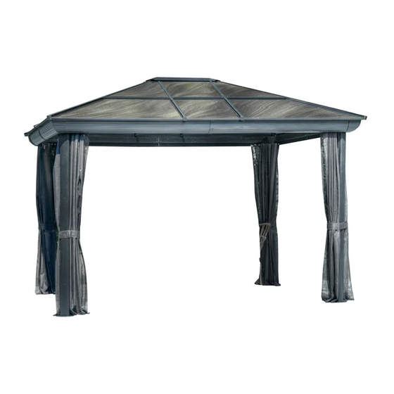
43202-22
BROWN
43202-32
SLATE
10'x12' GAZEBO
ASSEMBLY INSTRUCTIONS
DO NOT DESTROY THE BOXES UNTIL COMPLETELY ASSEMBLED
PLEASE VERIFY THE CONTENT OF EACH BOX AGAINST THE LIST OF PARTS
Assembly With More Than One Person Recommended
Base Dimensions 11' 3" x 8' 9"
APPROX.
Largest Dimensions 9'9" x 11'11"
Overall Height 108.5''
ZZZ-202.43202.0114-21.GP.EN.doc
WEB VERSION
1
Advertisement

Related Manuals for Gazebo penguin 43202-22


Summary of Contents for Gazebo penguin 43202-22
- Page 1 43202-22 BROWN 43202-32 SLATE 10’x12’ GAZEBO ASSEMBLY INSTRUCTIONS DO NOT DESTROY THE BOXES UNTIL COMPLETELY ASSEMBLED PLEASE VERIFY THE CONTENT OF EACH BOX AGAINST THE LIST OF PARTS Assembly With More Than One Person Recommended Base Dimensions 11’ 3” x 8’ 9”...
- Page 2 Some jurisdictions may require permits for, or otherwise regulate, installation and use. For assistance with assembly, installation, parts, or customer service, contact Gazebo Penguin Customer Service Department at the numbers listed below (English & French, Mon-Fri 8:00 AM to 4:00 PM EST):...
-
Page 3: Maintenance Notes
3. Leaking due to heavy rain may happen, please refer to the instruction manual for window positions and information on how to evacuate the water. 4. The product is only warranted in the event it is installed in accordance with the Gazebo Penguin’s written instructions enclosed with the product. - Page 4 Before You Assemble the Gazebo PLEASE DON'T DESTROY BOXES UNTIL COMPLETELY ASSEMBLED Please verify the content of each box against the list of parts. It is important that this gazebo be anchored on a solid base with the provided screws. Otherwise, please ensure that you use anchors sufficient for your surface.
- Page 5 ZZZ-202.43202.0114-21.GP.EN.doc WEB VERSION...
- Page 6 Step 2: For each leg “G”, attach foot plate “H” using 3 bolts “Pp”. Step 3: 1. Unscrew 4 Pp Bolts as shown below, have someone lift the Beam assembly and attach each Leg “G” into a Corner, again securing each using 4 Bolts “Pp”. 2.
- Page 7 Step 4: 1. Install Middle Cover “J” at each of the 4 beam junctions, using 4 Screws “Qq” each. 2. Install Corner Cover “I” at each of the corners, using 4 Screws “Qq” each. ZZZ-202.43202.0114-21.GP.EN.doc WEB VERSION...
- Page 8 Step 5: 1. Attach Mounting Brackets “O” and “P” to Rafters “M” and “N” respectively. Use threaded hole about 8 ½” & 5” from end of rafter. 2. Lift Central Hub “L” to a height of about 110” (2.79m) at the center of the gazebo. (Caution: this part may be heavy, use support as needed) 3.
- Page 9 Step 7: 1. Install the flashings “Q”, “R”, and “S” onto the beam assembly, using screws “Qq” on the inside. The notched end of a flashing will always go in a corner of the gazebo. Step 8: 1. Install the curtain rails “T” and “U” on the inside of the beam assembly using bolts “Pp”. ZZZ-202.43202.0114-21.GP.EN.doc WEB VERSION...
- Page 10 Step 9: 1. Slide the indicated polycarbonate panels into the spaces between the rafters, using the top groove of each rafter. Ensure the side meant to face the sun is on the outside. Use a rubber hammer to carefully tap each panel into the grooves.
- Page 11 Step 11: 1. Slide the remaining polycarbonate roof panels in the lower groove of the rafters and into the lower slot of the roof joints. Tap to make sure panels fit securely and do not extend past the ends of the rafters. Step 12: 1.
- Page 12 Step 13: 1. Install the upper crossbars on the interior of the roof using bolts “Pp”, following the shaped ends and letters. Do not tighten bolts immediately; install loose and tighten once all crossbars are in place. 2. Repeat this step with the lower crossbars.
-
Page 13: Important Notes
Step 15: Install the screen curtains “Ww” in the interior groove of the curtain rails, using the provided hooks. Install the privacy curtains “Xx” in the exterior groove of the rails. Once the hooks are in, use curtain rail caps “Uu” to close ends of curtain rails. IMPORTANT NOTES: Make sure all screws and bolts are tight. - Page 14 43200 BROWN (see page 17 for Slate parts) PACKED PACKED PART DIAGRAM PART DIAGRAM IN BOX IN BOX (11-624-22) (11-637-22) 52 ¾” 60 3/8” TOP LEFT ROOF BEAM RAFTER (12-030-22) (11-625-22) 52 ¾” RAFTER M TOP RIGHT MOUNTING BEAM BRACKET (12-031-22) (11-626-22) 65 ½”...
- Page 15 PACKED PACKED PART DIAGRAM PART DIAGRAM IN BOX IN BOX (11-644-22) 29 ½”x25 ½” (11-633-22) MIDDLE MIDDLE UPPER ROOF COVER PANEL (11-645-22) (11-634-22) 30”x30” 37 ¼” RIGHT UPPER TOP CAP ROOF PANEL (11-635-22) (11-646-22) 34 ¼” 30 ¾” CENTRAL LEFT MIDDLE ROOF JOINT (11-647-22) (11-636-22)
- Page 16 PACKED PACKED PART DIAGRAM PART DIAGRAM IN BOX IN BOX (11-652-22) 26 ¾” (08-193-22) CENTER PLASTIC PLUG EDGING (11-653-22) 58 7/8” (08-187-22) RIGHT WASHER (M6) EDGING (11-654-22) (11-697-22) RAFTER CURTAIN RAIL (11-655-22) CORNER (08-189-22) ACORN NUT BRACKET (11-656-22) 44” (11-695-22) Left LEFT SCREEN/MOU...
- Page 17 43200-32 SLATE PACKED PACKED PART DIAGRAM PART DIAGRAM IN BOX IN BOX (11-624-32) (11-637-32) 52 ¾” 60 3/8” TOP LEFT ROOF BEAM RAFTER (12-030-32) (11-625-32) 52 ¾” RAFTER M TOP RIGHT MOUNTING BEAM BRACKET (12-031-32) (11-626-32) 65 ½” RAFTER N TOP LEFT MOUNTING BEAM...
- Page 18 PACKED PACKED PART DIAGRAM PART DIAGRAM IN BOX IN BOX (11-644-32) 29 ½”x25 ½” (11-633-32) MIDDLE MIDDLE UPPER ROOF COVER PANEL (11-645-32) (11-634-32) 30”x30” 37 ¼” RIGHT UPPER TOP CAP ROOF PANEL (11-635-32) (11-646-32) 34 ¼” 30 ¾” CENTRAL LEFT MIDDLE ROOF JOINT (11-647-32) (11-636-32)
- Page 19 PACKED PACKED PART DIAGRAM PART DIAGRAM IN BOX IN BOX (11-652-32) 26 ¾” (08-193-32) CENTER PLASTIC PLUG EDGING (11-653-32) 58 7/8” (08-187-32) RIGHT WASHER (M6) EDGING (11-654-32) (11-697-32) RAFTER CURTAIN RAIL (11-655-32) CORNER (08-189-32) ACORN NUT BRACKET (11-656-32) 44” (11-695-32) Left LEFT SCREEN/MOU...
- Page 20 NOTE: The Dimensions Are Approximate. ZZZ-202.43202.0114-21.GP.EN.doc WEB VERSION...
Need help?
Do you have a question about the 43202-22 and is the answer not in the manual?
Questions and answers