Advertisement
Quick Links
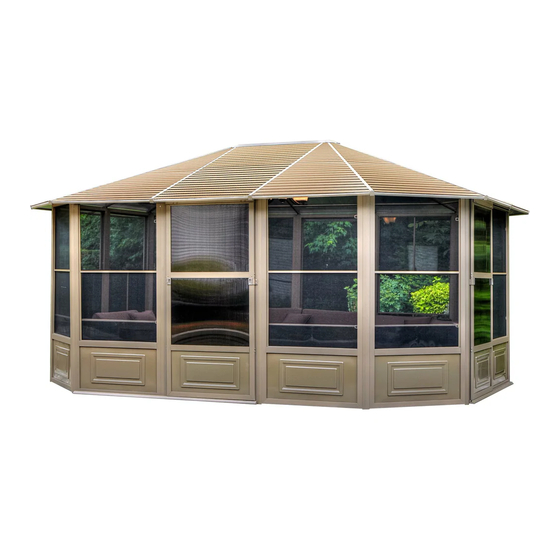
41215MR-12
SAND
41215MR-32
SLATE
12 X 15 SOLARIUM
ASSEMBLY INSTRUCTIONS
DO NOT DESTROY THE BOXES UNTIL COMPLETELY ASSEMBLED
PLEASE VERIFY THE CONTENT OF EACH BOX AGAINST THE LIST OF PARTS
Three adults required for assembly
Base Dimensions 12' ½"x15'6",
Largest Dimensions 12'10"x16'3"
APPROX.
Overall Height 110''
ZZZ-183.41215MR.0119-21.GP.EN.doc
WEB VERSION
1
Advertisement

Related Manuals for Gazebo penguin 41215MR-12


Summary of Contents for Gazebo penguin 41215MR-12
- Page 1 41215MR-12 SAND 41215MR-32 SLATE 12 X 15 SOLARIUM ASSEMBLY INSTRUCTIONS DO NOT DESTROY THE BOXES UNTIL COMPLETELY ASSEMBLED PLEASE VERIFY THE CONTENT OF EACH BOX AGAINST THE LIST OF PARTS Three adults required for assembly Base Dimensions 12’ ½”x15’6”, Largest Dimensions 12’10”x16’3”...
- Page 2 Some jurisdictions may require permits for, or otherwise regulate, installation and use. For assistance with assembly, installation, parts, or customer service, contact Gazebo Penguin Customer Service Department at the numbers listed below (English & French, Mon-Fri 8:00 AM to 4:00 PM EST):...
- Page 3 Leaking due to heavy rain may happen, please refer to the instruction manual for window positions and information on how to evacuate the water. The product is only warranted in the event it is installed in accordance with the Gazebo Penguin’s written instructions enclosed with the product.
- Page 4 41215MR SAND (See page 8 for Slate parts) DRAWING DRAWING 08-129-12 08-132-12 REGULAR SLIDING FRAME DOOR FRAME 17-054 08-165-12 ROOF DOOR LATCH PANEL Dd-R 08-130-12 FRAME 08-169-12 NEXT TO DOOR LATCH DOORS Dd-L (extra holes) 08-158-12 08-133-12 SCREW CONNECTING PIECE 78.9’’ M6*16 08-131-12 08-167-12...
- Page 5 DRAWING DRAWING 17-061 08-187-12 ROOF WASHER PANEL 08-138-12 17-044-12 DOOR RAFTER 78.9’’ STOPPER 17-057 08-189-12 ROOF ACORN NUT PANEL 08-139-12 08-179-12 CONNECTING TOP CAP PIECE 78.9’’ 08-193 17-058 PLASTIC ROOF PLUG PANEL 08-140-12 08-178-12 CENTRAL CONNECTING PIECE 78.9’’ 08-134-12 17-055 UPPER ROOF DOOR RAIL...
- Page 6 DRAWING DRAWING 17-050-12 17-046-12 COVER FOR FINISHING RAFTER BAR 45.3’’ 78.5’’ 17-068-12 08-135-12 FINISHING SCREW BAR 42.6’’ 16-118-12 17-048-12 SCREW SOLIDIFYING BAR 20.8’’ M6 X 36 17-051-12 17-069-12 GAP COVER SOLIDIFYING BAR 39.4’’ BAR 39.7’’ 18-067-12 17-045-12 SOLIDIFYING FINISHING BAR 45.2’’ BRACKET 17-075 17-071-12...
- Page 7 DRAWING DRAWING 15-124-12 12-047-12 STEEL SCREW ANGLE M5 X 15 (assembled on rafter) 15-125-12 17-060 STEEL ROOF ANGLE PANEL (assembled on rafter) *NOT INCLUDED IN THE BOX 08-156-12 DESCRIPTION COLOUR PART # SCREW SPRAY PAINT 11-699 M4 X 16 SAND PAINT PEN 18-245 ZZZ-183.41215MR.0119-21.GP.EN.doc...
- Page 8 41215MR SLATE DRAWING DRAWING 08-129-32 08-132-32 REGULAR SLIDING FRAME DOOR FRAME 17-054 08-165-32 ROOF DOOR LATCH PANEL Dd-R 08-130-32 FRAME 08-169-32 NEXT TO DOOR LATCH DOORS Dd-L (extra holes) 08-158-32 08-133-32 SCREW CONNECTING PIECE 78.9’’ M6*16 08-131-32 08-167-32 SLIDING SCREW DOOR M6*63.5 08-161-32...
- Page 9 DRAWING DRAWING 08-187-32 17-061 WASHER ROOF PANEL 08-138-32 17-044-32 DOOR RAFTER 78.9’’ STOPPER 08-189-32 17-057 ROOF PANEL ACORN NUT 08-139-32 08-179-32 CONNECTING TOP CAP PIECE 78.9’’ 08-193 17-058 PLASTIC ROOF PANEL PLUG 08-140-32 08-178-32 CENTRAL CONNECTING PIECE 78.9’’ 08-134-32 17-055 UPPER ROOF PANEL DOOR RAIL...
- Page 10 DRAWING DRAWING 17-050-32 17-046-32 COVER FINISHING FOR RAFTER BAR 45.3’’ 78.5’’ 17-068-32 08-135-32 FINISHING SCREW BAR 42.6’’ 16-118-32 17-048-32 SCREW SOLIDIFYING BAR 20.8’’ M6 X 36 17-051-32 17-069-32 GAP COVER SOLIDIFYING BAR 39.4’’ BAR 39.7’’ 18-067-32 17-045-32 SOLIDIFYING FINISHING BAR 45.2’’ BRACKET 17-071-32 17-075...
- Page 11 DRAWING DRAWING 15-124-32 12-047-32 STEEL SCREW ANGLE M5 X 15 (assembled on rafter) 15-125-32 17-060 STEEL ROOF ANGLE PANEL (assembled on rafter) *NOT INCLUDED IN THE BOX 08-156-32 DESCRIPTION COLOUR PART # SCREW SPRAY PAINT 18-125 M4 X 16 SLATE PAINT PEN 18-126 ZZZ-183.41215MR.0119-21.GP.EN.doc...
- Page 12 Before you assemble the Solarium PLEASE DON'T DESTROY BOXES UNTIL COMPLETELY ASSEMBLED Tools needed: Step Ladder 6’ – 8’ #2 Phillips Screwdriver, Robertson #2 (not supplied) Rubber Mallet Various Files 12” piece of wood Based on the location, decide where you would like to position the two (2) doors panels which can slide open to the left or the right, your choice.
- Page 13 Assembly Instructions 12x15 Solarium Pre-assembled steel angle (Z1, Z2) to roof Rafters (K, L) respectively using Bolts (Bb) To Be Assembled Before Packing 4 Steel Angles (Z1) to be attached to the right hole and remaining 4 to the left hole. ZZZ-183.41215MR.0119-21.GP.EN.doc WEB VERSION...
- Page 14 Step 1: Before starting to assemble, please decide where you would like to position the door panels. 1. Stand up two Regular Frames (A) and affix the panels together at an angle by sliding two connecting Pieces (I, J) from top to bottom. 2.
- Page 15 Step 2: Affix gap Cover Bars (P) by sliding them on the top of the exterior groove of the Regular Frames (A, B, D). ZZZ-183.41215MR.0119-21.GP.EN.doc WEB VERSION...
- Page 16 Step 3: Slide Top Door Rail (F) into wheels of Sliding Door (C). Slide Lower Door Rail (G) into the plastic guide of the Sliding Door (C). Use Bolts (Bb) to affix the Plastic Stoppers (H) one on each end of Top Door Rail (F). 4.
- Page 17 Step 4: Please note the sliding door is suggested to be installed from the inside of the solarium. 1. Place a Bolt (Ww) and Washer (Gg) through the Top Door Frame (D) and Door Top Rail (F), and place a Female Bolt (Cc-2) from the other side. Once all are inserted, tighten them all securely. 2.
- Page 18 Step 5: 1. Attach roof Rafters (L) to the Central Hub (N) using Bolts (Bb). 2. Use Screws (Z) to affix the Rafters (L) onto the top of panels going through the Metal Piece (Z2) attached to the Rafter (L). Note: Do not tighten the bolts right away as you may have to adjust the angle when inserting the roof panels.
- Page 19 Step 6: 1. Follow the same procedure of Rafter (L) to assemble roof Rafters (K) onto the remaining panels. Note: 1. Rafters must be affixed where panels connect to each other. 2. Affix the Rafter (K) such that, the extra hole on the bracket (Z1) are facing each other as shown below.
- Page 20 Step 7: Now secure the sides of the roof with Finishing Bar (S, U, Ss and U1) with Bolts (Bb) and Brackets R. Place roof Finishing Bars (S, U, Ss and U1) on the right of the Roof Finishing Bar (S, U, and U1) and align the holes in each bar one on top of the other.
- Page 21 Step 8: From the inside of the solarium, install all the Brackets (Pp) using Bolts (Bb) on the Rafters L & K. From the inside of the solarium, install the Solidifying Bar (T, Tt , V, and V1) as illustrated using the Bolts (Bb).
- Page 22 Step 9: Install the bottom Roof Panels (Jj, Kk, Mm, Rr) by sliding them onto Finishing Bar (S, U, Ss & U1). NOTE: Please refer to the stickers on how to place the roof panels . Make sure all screws/ bolts are tight. ZZZ-183.41215MR.0119-21.GP.EN.doc WEB VERSION...
- Page 23 Step 10: Install the upper Roof Panel (Aa) by sliding them on top of roof Rafters (K). NOTE: Please refer to the stickers on how to place the roof panels. ZZZ-183.41215MR.0119-21.GP.EN.doc WEB VERSION...
- Page 24 Step 11: Once installation of the Roof Panel (Aa) is complete, affix it using the Cover for Rafters (0) using the Screws (Oo1) on one side only, then place another roof panel and repeat this step. ZZZ-183.41215MR.0119-21.GP.EN.doc WEB VERSION...
- Page 25 Step 12: Install the Upper Roof Panels (Aa, Ll, Qq, Y) by sliding on top of roof Rafters (K, L) except for one Roof Panel (Qq) while installing Cover for Rafters(0 & 01). ZZZ-183.41215MR.0119-21.GP.EN.doc WEB VERSION...
- Page 26 Step 13: Use Nut (Hh) and Washer (Gg) to affix the Top Cap (M) to the Central Hub (N). ZZZ-183.41215MR.0119-21.GP.EN.doc WEB VERSION...
- Page 27 Step 14: Install the last upper Roof Panel (Qq). ZZZ-183.41215MR.0119-21.GP.EN.doc WEB VERSION...
- Page 28 Step 15: Once the last roof panel is installed, affix the Cover for Rafter (O1) to the Rafters (L) with Bolt (Oo1). ZZZ-183.41215MR.0119-21.GP.EN.doc WEB VERSION...
- Page 29 Step 16: Inside each of the frames panels, push two Plastic Plugs (Ii) into the ground, and secure the unit by using two Screws (Ee) for each panel or use any other type of anchoring suitable for the floor that you are using.
- Page 30 Suggestions The below mentioned are only suggestions in order to permit drainage, these will vary depending on your flooring – material, flatness and slope. ZZZ-183.41215MR.0119-21.GP.EN.doc WEB VERSION...
- Page 31 ZZZ-183.41215MR.0119-21.GP.EN.doc WEB VERSION...
- Page 32 NOTE: The dimensions are approximate. ZZZ-183.41215MR.0119-21.GP.EN.doc WEB VERSION...
Need help?
Do you have a question about the 41215MR-12 and is the answer not in the manual?
Questions and answers