
Subscribe to Our Youtube Channel
Related Manuals for Lanner FW-7551


Summary of Contents for Lanner FW-7551
- Page 1 Network Application Platforms Hardware platforms for next generation networking infrastructure FW-7551 V1.3 User's Manual >> Date (Y/M/D): 2017/05/09...
- Page 2 Resource Website accordance with the instruction manual, may cause harmful interference to radio communications. Operation Lanner http://www.lannerinc.com of this equipment in a commercial area is likely to cause harmful interference in which case the user will be required Product http://www.lannerinc.com/download-...
- Page 3 About About Consignes de sécurité LITHIUM BATTERY CAUTION: Risk of Explosion if Battery is replaced by an incorrect type. Suivez ces consignes pour assurer la sécurité générale : Dispose of used batteries according to the instructions • Laissez la zone du châssis propre et sans poussière pendant et après l’installation.
- Page 4 About About Sécurité de fonctionnement Cet appareil de protection doit être branché à la source d’alimentation avant l’alimentation CC. • L’équipement électrique génère de la chaleur. La température ambiante peut ne pas être adéquate pour refroidir l’équipement à une température de fonctionnement acceptable sans circulation adaptée.
-
Page 5: Table Of Contents
Lanner Generation 2 Bypass........ -
Page 6: Chapter 1: Introduction
Ethernet Modules N/A Management Port N/A The system also features 6 GbE ports. In addition, the 4 1 x reset button (of all 6) LAN ports are equipped with Lanner proprietary Reset Button Software reset by default Generation 2 bypass. -
Page 7: Ordering Information
36W Power Adapter Power Your package contains the following items: Input 100~240V@50~60Hz Approvals and Compliance CE, FCC Class B, RoHS • FW-7551 Network Security Platform • Power cable Ordering Information • 1 console cable • Drivers and user’s manual CD. -
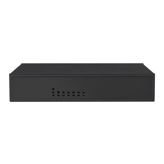
Page 8: Front Panel Features
Chapter 1 Introduction Front Panel Features F1 Power/Status/HDD LED Power: If the LED is on it indicates that the system is powered on. If it is off, it indicates that the system is powered off. Status: This LED is programmable. You could program it to display the operating status with the following behavior: If the LED is green, it indicates that the system’s operational state is normal. -
Page 9: Rear Panel Features
BIOS; the default is disabled). Two pairs (LAN3-LAN4, LAN5-LAN6) can be configured as LAN Bypass by using Lanner Gen2 Bypass technology when failure events occur. This feature can be enabled dynamically with a watch dog timer. Refer to your User’s Manual CD for a sample implementation of this feature. -
Page 10: Chapter 2: Hardware Setup
3. Slide the cover backwards to open it. The system can accommodate one 2.5” Serial-ATA disk. Follow these steps to install a hard disk into the FW-7551: 1. Unscrew the 4 screws on the hard disk tray to take out the hard disk tray from the system. -
Page 11: Installing The Compactflash Card
Hardware Setup Installing the CompactFlash Card 2.5” HDD installation FW-7551 provides one CompactFlash slot. Follow the procedures bellow for installing a CompactFlash card. 1. Align CompactFlash card and the card slot with the arrow pointing toward the connector. The card fits only the correct way into the slot;... -
Page 12: Chapter 3: Motherboard Information
Chapter 3 Motherboard Information Chapter 3: Motherboard Information Block Diagram The block diagram depicts the relationships among the interfaces or modules on the motherboard. Please refer to the following figure for your motherboard’s layout design. MB-7551 1x or 2x DDR3/L 1333 / 1600 MHz Dual Channel DDR3 1333/1600 MHz 204-pin SO-DIMM... -
Page 13: Motherboard Layout
Chapter 3 Motherboard Information Motherboard Layout The motherboard layout shows the connectors and jumpers on the board. Refer to the following picture as a reference of the pin assignments and the internal connectors. GPIO1 LPC1 FAN1 USB2 DIMM1 PKMB1 COM1 USB1 SATA6G_1 SATA6G_2... -
Page 14: Jumper Settings
Chapter 3 Motherboard Information Jumper Settings USB Connector(USB2): It is for connecting the USB module cable. It complies with USB2.0 and support Fan Connectors(FAN1 ): The 3-pin connector is for up to 480 Mbps connection speed. connecting the CPU fan. Pin No. - Page 15 Chapter 3 Motherboard Information GPIO Output Pin (J10): Theses pins can be used to write CompactFlash Connector (CF1): It is for connecting a to an internal register to control the GPIO output pin Compact Flash card to be served as your system’s state.
- Page 16 Chapter 3 Motherboard Information DIMM Socket (DIMM1): The 204-pin DDR3 SO-DIMM is 4-Pin SATA Power Connector (PS4P1) for connecting the DDR3 1333/1600 ECC memory. The system can support up to 8 GB in maximum. Pin No. Signal +12V Ground AT-Mode Power Button Connector (J21) It is for SATA Connector (SATA6G_1, SATA6G_2): It is for connecting the power switch in AT mode.
- Page 17 Chapter 3 Motherboard Information PCIe Expansion Connector (MPCIEC1): Mini-PCIe connector PIN NO. FUNCTION PIN NO. FUNCTION PMU_WAKE# VCC3 1.5V NC_RSV1 SMB_CLK NC_RSV2 MINI_PCIE_TXN0 1.5V SMB_DATA MINI_CLKREQ_N1 MINI_PCIE_TXP0 NC_UIM_PWR NC_UIM_DATA USB_IO3_DN MINIPCIE_REFCLKN NC_UIM_CLK USB_IO3_DP MINIPCIE_REFCLKP VCC3 NC_UIM_RST VCC3 NC_UIM_VPP NC_LED_WWAN# NC_RSV3 NC_LED_WLAN# NC_RSV4 NC_RSV9...
-
Page 18: Chapter 4: Bios Settings
Chapter 4 Bios Settings Chapter 4: keys, and so on. BIOS Settings Accessing the BIOS menu When you are installing a motherboard or when the system prompts “Run Setup” during start-up, you will use the BIOS Setup program to configure the system, . This section explains how to configure your system using this program. -
Page 19: The Main Menu
Chapter 4 Bios Settings The Main Menu The main BIOS setup menu is the first screen that you can navigate. Each main BIOS setup menu option is described in this chapter. The Main BIOS setup menu screen has two main frames. The left frame displays all the options that can be configured. -
Page 20: Advanced Settings
Chapter 4 Bios Settings Advanced Settings Select the Advanced tab from the setup screen to enter the Advanced BIOS Setup screen. You can select any of the items in the left frame of the screen, such as SuperIO Configuration, to go to the sub menu for that item. You can display an Advanced BIOS Setup option by highlighting it using the <Arrow>... - Page 21 Chapter 4 Bios Settings Super IO configuration Serial Port 0/1 Configuration Item Selection Serial Port Enable or disable this serial port Device Shows the serial port base address and the IRQ Settings port Change Selects the port base address and the IRQ port Settings Parallel port Configuration Item...
- Page 22 Chapter 4 Bios Settings W83627DHG HW Monitor This menu shows the hardware monitor configuration settings. Select an item then press <Enter> to display the configuration options. PC Health Status SYS/CPU/AUX Temperature The onboard hardware monitor automatically detects and displays the CPU and motherboard temperatures. CPUFAN0 Speed (CPU FAN) The onboard hardware monitor automatically detects and displays the CPU fan speeds in rotations per minute (RPM).
- Page 23 Chapter 4 Bios Settings Console Redirection Use this menu to set the settings for BIOS remote access feature. Item Selection Console Redirection Enable or disable BIOS through remote access Console Redirection Set- Enter to view more options tings COM0 Console Redirection Settings Item Selection Terminal Type...
- Page 24 LAN Bypass function, refer to the Front Panel Feature in Chapter 1 Introduction. Note: the Ethernet expansion module may support Lanner Generation 2 or Generation 3 Bypass depending on the module specification. See appendix D Programming Generation 2 and 3...
- Page 25 Chapter 4 Bios Settings USB Configuration You can use this screen to select options for the USB Configuration. Use the up and down <Arrow> keys to select an item. Use the <Plus> and <Minus> keys to change the value of the selected option. The settings are described on the following pages.
- Page 26 Chapter 4 Bios Settings USB Mass Storage Driv In this option, you can enable or disable the attached USB drive to be used as the system’s hard drive. USB Hardware Delays a The menu sets delay time for USB operations. Item Description USB transfer...
-
Page 27: Intel Rcsetup
Chapter 4 Bios Settings Intel RCSetup You can use this screen to view the capabilities and of your CPU. You can also use this menu to enable/disable certain functions of your CPU. Use the up and down <Arrow> keys to select an item. Use the <Plus> and <Minus> keys to change the value of the selected option. - Page 28 Chapter 4 Bios Settings North Bridge Chipset Configuration It shows the memory information such as the total detected memory and memory frequency. South Bridge Chipset Configuration Restore on AC Power Loss This option lets you set the state of the system when it has just recovered from a power outage.
- Page 29 Chapter 4 Bios Settings Item Selection AHCI Mode Set to AHCI mode when you want the SATA hard disk drives to use the AHCI (Advanced Host Controller Interface). The AHCI allows the onboard storage driver to enable advanced SATA features that increases storage performance or workloads where multiple simultaneous read/write requests are outstanding, most often occurring in server-...
-
Page 30: Security Settings
Chapter 4 Bios Settings Security Settings Select Security Setup from the Setup main BIOS setup menu. All Security Setup options, such as password protection and virus protection, are described in this section. To access the sub menu for the following items, select the item and press <Enter>: Administrator Password If you have set an administrator password, you should... -
Page 31: Boot Configuration
Chapter 4 Bios Settings Boot Configuration In this screen, you will be able to configure the boot procedures and the related elements. Items Options Setup Prompt Timeout Specify the number of seconds for the boot setup prompt to wait for user’s intervention during the POST. -
Page 32: Save & Exit
Chapter 4 Bios Settings Save & Exit Save and Exit Select the Exit tab from the setup screen to enter the Exit BIOS Setup screen. You can display an Exit BIOS Setup option by highlighting it using the <Arrow> keys. The following table lists the options in this menu. -
Page 33: Appendix A: Programming Watchdog Timer
Appendix A Programming Watchdog Timer Appendix A: Programming Watchdog Timer A watchdog timer is a piece of hardware that can be used to automatically detect system anomalies and reset the processor in case there are any problems. Generally speaking, a watchdog timer is based on a counter that counts down from an initial value to zero. -
Page 34: Appendix B: Setting Up Console Redirections
Appendix B Setting up Console Redirection Appendix B: Setting up Console Redirections Console redirection lets you monitor and configure a system from a remote terminal computer by re-directing keyboard input and text output through the serial port. This following steps illustrate how to use this feature. The BIOS of the system allows the redirection of console I/O to a serial port. -
Page 35: Appendix C: Programming Generation 2 Lan Bypass
Lanner Generation 2 Bypass Bypass settings LAN Bypass for Port1 and LAN Bypass Port 2 1&2 when System Status power off Lanner Generation 2 bypass is configured through the Enabled Disabled Disabled BIOS menu as shown below: PWR ON Non-Bypass Non-Bypass PWR OFF Non-Bypass Non-Bypass 2. -
Page 36: Appendix D: Installing Intel Quickassist Software For Linux
Intel® QuickAssist Technology Appendix D: Installing Intel QuickAssist Software for Linux The FW-7551 platform incorporates Intel QuickAssist Technology, which includes acceleration modules that are accessed via Intel QuickAssist software. The Intel quickAssist software also enables the acceleration modules to be easily accessed by open source software such as OpenSSL. -
Page 37: Appendix E: Terms And Conditions
Appendix E Terms and Conditions Appendix E: RMA Service Terms and Conditions Requesting a RMA# 6. To obtain a RMA number, simply fill out and fax the “RMA Request Form” to your supplier. Warranty Policy 7. The customer is required to fill out the problem code as listed. - Page 38 Appendix E Terms and Conditions RMA Service Request Form When requesting RMA service, please fill out the following form. Without this form enclosed, your RMA cannot be processed. Reasons to Return: □ Repair(Please include failure details) RMA No: □ Testing Purpose Company: Contact Person: Phone No.
Need help?
Do you have a question about the FW-7551 and is the answer not in the manual?
Questions and answers