Advertisement
Quick Links
Advertisement

Subscribe to Our Youtube Channel
Related Manuals for Lanner FX-3230


Summary of Contents for Lanner FX-3230
- Page 1 Network Appliance Platform FX-3230 User Manual Version: 1.0 Date of Release:2019-02-14...
- Page 2 Product Resource http://www.lannerinc.com/download-center http://eRMA.lannerinc.com This document is copyrighted © 2020 by Lanner Electronics Inc. All rights are reserved. The original manufacturer reserves the right to make improvements to the products described in this manual at any time without notice. No part of this manual may be reproduced, copied, translated or transmitted in any form or by any means without the prior written permission of the original manufacturer.
- Page 3 FX-3230 User Manual This product has passed the CE test for environmental specifications. Test conditions for passing included the equipment being operated within an industrial enclosure. In order to protect the product from being damaged by ESD (Electrostatic Discharge) and EMI leakage, we strongly recommend the use of CE- compliant industrial enclosure products.
-
Page 4: Lithium Battery Caution
FX-3230 User Manual In order not to result in potential electric shock or fire, please avoid improper use narrated below: Replacing a battery with an incorrect type (e.g. in the case of certain lithium battery types), which can defeat a safety guard. - Page 5 The installation of this product must be performed by trained specialists; otherwise, a non-specialist might create the risk of the system’s falling to the ground or other damages. Lanner Electronics Inc. shall not be held liable for any losses resulting from insufficient strength for supporting the system or use of inappropriate installation components.
- Page 6 FX-3230 User Manual L’installation doit être effectuée par un électricien formé ou une personne formée à l’électricité connaissant toutes les spécifications d’installation et d’appareil du produit. Ne transportez pas l’unité en la tenant par le câble d’alimentation lorsque vous déplacez l’appareil.
- Page 7 FX-3230 User Manual Desserrez la vis du terminal de mise à la terre. Branchez le câble de mise à la terre à la terre. L’appareil de protection pour la source d’alimentation CC doit fournir 30 A de courant. Cet appareil de protection doit être branché à la source d’alimentation avant l’alimentation CC.
- Page 8 FX-3230 User Manual...
- Page 9 FX-3230 User Manual Package Content ......................... 11 Ordering Information ......................... 11 Optional Accessories ........................11 System Specifications ......................... 12 Front Panel ..........................13 Rear Panel ........................... 15 Block Diagram ..........................16 Motherboard Layout ........................17 Internal Jumper & Connectors ....................18 Opening the Chassis ........................
- Page 10 FX-3230 User Manual Advanced Setup .......................... 48 Platform Setup ..........................71 Socket Setup ..........................75 Server Mgmt ..........................85 Security ............................90 Boot Setup ..........................93 Save and Exit Setup ........................94 Why Dual BIOS? .......................... 97 How Dual BIOS Works ........................ 98 Warranty Policy ........................
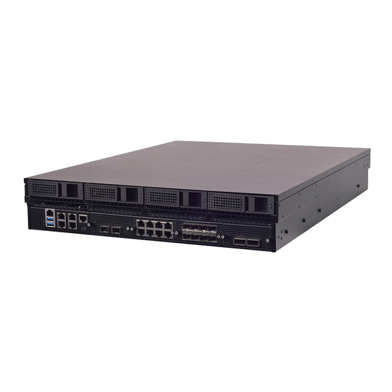
- Page 11 FX-3230 User Manual The FX-3230 is a secure, high-performance and high-capacity 2U rackmount storage gateway appliance built with Intel® Xeon® Processor Scalable Family (Skylake-SP). It comes with Intel® QuickAssist Technology and can be configured with up to 320GB of system memory, 4x 3.5” swappable HDD bays, 1x onboard mSATA slot, 4x GbE RJ45 or 4x 10G SFP+, 4x NIC module slots, 1x RJ45 &...
- Page 12 FX-3230 User Manual Form Factor 2U 19“ Rackmount Intel® Xeon® Processor Scalable Family Processor Options (Skylake-SP) Platform CPU Socket 1x LGA3647 Chipset Intel® C621/626/627 Security Acceleration Intel® QuickAssist Technology (By SKU) BIOS AMI SPI Flash BIOS Technology DDR4 2666 MHz REG DIMM System Memory Max.
- Page 13 FX-3230 User Manual...
- Page 14 FX-3230 User Manual...
- Page 15 FX-3230 User Manual...
- Page 16 FX-3230 User Manual The block diagram indicates how data flows among components on the motherboard. Please refer to the following figure for your motherboard’s layout design.
- Page 17 FX-3230 User Manual The motherboard layout shows the connectors and jumpers on the board. Refer to the following picture as a reference of the pin assignments and the internal connectors. ATX1 ATX4 ATX5 ATX6 CONN1 ATX2 ATX3 JPWR1 JATX3 JLCM1...
- Page 18 FX-3230 User Manual JRST1: Setting Description Setting Description HW reset SW reset...
- Page 19 FX-3230 User Manual JTPM1: Supports TPM 1.2 & 2.0 Description Description IRQ_SERIAL LPC_LFRAME# LPC_LAD0 CLK_24M_LPC LPC_LAD1 +P3V3_AUX LPC_LAD2 LPC_LAD3 +P3V3 TPM_RST# JVGA1 Description Description DAC_RO DAC_GO DAC_BO HSYNC_O VSYNC_O DDC_DATA DDC_CLK ATX6: 8-Pin Power Connector Description Description +P5V +P5V_SB +P12V_STBY_PSU...
- Page 20 FX-3230 User Manual JATX8: 4 pin Power Connector (12V standby) Description Description +P12V_1_STBY +P12V_1_STBY JATX2 & JATX4: 8 pin Power Connector Description Description +12V +12V +12V +12V JATX9: 4 pin Power Connector (12V standby) Description Description +P12V_2_STBY +P12V_2_STBY JSATA1~JSATA4: SATA Port...
- Page 21 FX-3230 User Manual MSATA1: Description Description Description Description RSV1 GND1 WAKE# +3.3Vaux1 CLKREQ UIM_PWR RSV2 +1.5V1 REFCLK- UIM_CLK GND2 UIM_DATA GND3 UIM_VPP REFCLK+ UIM_RESET RSV4 W_DISABLE# RSV3 GND4 PERn0 +3.3Vaux2 GND5 PERST# GND7 +1.5V2 PERp0 GND6 PETn0 SMB_DATA GND8 SMB_CLK...
- Page 22 FX-3230 User Manual GND10 USB_D- PETp0 GND9 +3.3Vaux4 GND11 GND13 USB_D+ GND14 LED_WLAN# +3.3Vaux5 LED_WWAN# RSV10 +1.5V3 RSV9 LED_WPAN# RSV12 +3.3Vaux3 RSV11 GND12 JCOM2: COM PORT Description Description BMC_COM2_DCD# BMC_COM2_DSR# BMC_COM2_RX BMC_COM2_RTS BMC_COM2_TX BMC_COM2_CTS# BMC_COM2_DTR BMC_COM2_RI# COM2_GND2 JLCM1: UART2 Description...
- Page 23 FX-3230 User Manual JOPEN1: Case open Description Description FM_INTRUDER#...
- Page 24 FX-3230 User Manual JCMOS1: Clear CMOS Description Description VRTC PCH_RTCRST# Normal (Default) Clear CMOS JSPIROM1: Flash BIOS Description Description SPI_HD1# SPI_CS1#_DUAL SPI_CS0#_DUAL +P3V3_SPI_ME SPI_MISO SPI_PCH_IO3 SPI_CLK SPI_MOSI JGP1: EXT GPIO header Description Description GPO_B_1 GPI_B_1 GPO_B_2 GPI_B_2 GPO_B_3 GPI_B_3 GPO_B_4...
- Page 25 FX-3230 User Manual JIOB1: IO board...
- Page 26 Also, please wear ESD protection gloves when conducting the steps in this chapter. 1. Loosen the 2 thumb screws from the rear panel of FX-3230. 2. Gently pull the cover backward a bit.
- Page 27 FX-3230 User Manual Please note that the system delivered to you is already installed with the processor and that this processor, LGA3647, comes with rather sophisticated design; therefore, the assembly of which must be handled with exclusive tools and extreme care by professionals. It is strongly recommended that you not make any adjustments to, remove or even re-install the processor on your own.
- Page 28 FX-3230 User Manual If a TIM (Thermal Interface Material) protective film is already attached to the base of the heat sink, remove it before you mount the processor Heat Sink on it. When holding it, please grip it along the axis of Axis its fins with your thumb and your index finger.
- Page 29 FX-3230 User Manual 1. Align the PIN1 indicator on the processor with that on the carrier. Gently insert one side of the processor into the carrier and make sure the alignment feature is aligned with the latch of the carrier.
- Page 30 FX-3230 User Manual 4. Align PIN1 of the processor with the corner cutout of the heat sink (if Cutout there are two corner cutouts on one heat sink, either will do). 5. With a little pressure, push the four corners of the carrier down to...
- Page 31 FX-3230 User Manual 2. Flip the PHM over to align PIN1 the carrier with the Cutout of the Cutout bolster plate. 3. Flip the PHM over, with the package Alignment Pin land of the processor facing the socket, carefully hold the PHM while...
- Page 32 FX-3230 User Manual Note: When fastening #3 and #4 nuts, the gap between the metal spring leaf of the bolster plate and the PHM will gradually diminish as you drive the nuts.
- Page 33 FX-3230 User Manual FX-3230 is built with two 3.5” HDD/SSD slot (HDD preferred) drive bay. The following will discuss disk drive installation procedures based on their HDD/SSD designs. 1. Power off the system. 2. Locate the 3.5” disk bay on the front panel.
- Page 34 FX-3230 User Manual FX-3230 comes with 8 NIC Ethernet module slots for network bandwidth expansion. Please follow the steps for installation. 1. On the front panel, select a NIC Ethernet module slot. 2. Rotate clockwise and loosen the two lock-screws.
- Page 35 FX-3230 User Manual 4. Insert your NIC Ethernet module. (The module shown in the image below is for reference only). Align the golden fingers to th e PCIe socket motherboard efully while inserting this module. 5. Once the module is firmly seated, rotate counter-clockwise and tighten the two lock-screws.
- Page 36 FX-3230 User Manual Cooling fans may wear down eventually. Please refer to the steps below for replacing cooling fans. When using a new cooling fan, simply reverse the steps to install the fan back onto the enclosure and the system.
- Page 37 FX-3230 User Manual 4. Remove the 4 screws that secure the fan. 5. Remove the 4 screws that enclose the fan. 6. Take the fan connector out of the enclosure. 7. Take the worn cooling fan out.
- Page 38 FX-3230 User Manual Power supply units may wear down eventually. Please be noted that FX-3230 series supports 550W/800W depending on the ordering preferences. Please prepare the power supply units matching this capacity. 1. On the rear panel, locate the power supply units and disconnect the power cords.
- Page 39 FX-3230 User Manual The motherboard provides one mSATA slot. Follow the procedures below for installing an mSATA card. 1. Locate the mSATA socket. Align the notch of the DIMM module with the socket key in the slot. Notch Socket Key 2.
- Page 40 FX-3230 User Manual The motherboard supports DDR4 registered DIMM memory for heavy-duty operations. Please follow the steps below to install the DIMM memory modules. The primary CPU and the secondary CPU both have 10 DIMM sockets (5 on its both sides), If you do not plan to fill up all the sockets with 20 memory modules, always start with the blue ones for optimal performance.
- Page 41 FX-3230 User Manual There are two methods for installing this system in a rack: With Mounting Ear Brackets This method is quick and easy by fixing this system to the front posts of the rack, but it also makes servicing the system more difficult.
- Page 42 FX-3230 User Manual 1. Check the package contents. The mounting brackets shall For securing the brackets on the rack posts include the items below: For securing the brackets on 1x Screw Pack the unit 2x Ear Brackets 2. Secure the bracket onto one side of the chassis using six provided screws.
- Page 43 FX-3230 User Manual 1. Check the package contents of the Slide Rail Kit. The kit shall include the following items: 1x pack of M4X4L screws (for securing the sliding rail on the system) 1x pack of 7.1 Round Hole screws (for securing the system on...
- Page 44 FX-3230 User Manual 5. Align the bracket to the side of the chassis make sure screw-holes are matched, and then secure the bracket onto the chassis with five provided M4X4L screws. Align the screws with the indicate d holes on the brackets as well as the screw holes on the sid e of the chassis.
- Page 45 FX-3230 User Manual Installing the Slide Rails Now, you shall install the slide rail assemblies onto the rack. 9. This slide-rail kit does NOT require screw-fixing. Simply aim at 3 Click available screw holes on the rack front and snap the rail front into...
- Page 46 FX-3230 User Manual 12. Hold the system with its front facing you, lift the chassis and gently engage the brackets on the model while aligning them with the slide-rail assemblies as shown in the image below, and then push the system into the cabinet.
- Page 47 FX-3230 User Manual Note: Make sure that the system air vents have sufficient airflow from front to rear when the system is mounted in a rack. If the system vents are blocked, the system might be damaged due to overheat.
- Page 48 FX-3230 User Manual To enter the BIOS setup utility, simply follow the steps below: 1. Boot up the system. 2. Pressing the <Tab> or <Del> key immediately allows you to enter the Setup utility, then you will be directed to the BIOS main screen. The instructions for BIOS navigations are as below:...
- Page 49 FX-3230 User Manual Item Description BIOS Vendor : American Megatrends Core Version : AMI Kernel version, CRB code base, X64 Compliancy : UEFI version, PI version BIOS Information Project Version: BIOS release version Build Date and Time: MM/DD/YYYY Access Level: Administrator / User To set the Date, use <Tab>...
- Page 50 FX-3230 User Manual Use [→] or [←] to select [Advanced] setup screen. Under this screen, you may use [↑] [↓] to select an item you want to configure.
- Page 51 FX-3230 User Manual Item Description The worldwide unique name of iSCSI Initiator. Only IQN format is accepted. iSCSI Initiator Name The range is from 4 to 223.
- Page 52 FX-3230 User Manual This option allows you to check RAID volume management information supported by Intel® Virtual RAID on CPU (Intel® VROC). Press <Enter> access the submenu.
- Page 53 FX-3230 User Manual This option allows you to configure parameters regarding BIOS support for security device. Press <Enter> to access the submenu. Item Option Description Select “Enable “or “Disable “to turn on or off the BIOS support for Security Device. The default is “Enabled “. By...
- Page 54 FX-3230 User Manual Trusted Computing (TPM1.2) Item Option Description Security Enables or disables BIOS support for security device. By Enabled Device disabling this function, OS will not show Security Device. Disabled Support TCG EFI protocol and INT1A interface will not be available.
- Page 55 FX-3230 User Manual Trusted Computing (TPM2.0)
- Page 56 FX-3230 User Manual Item Option Description Security Enables or disables BIOS support for security device. By Enabled Device disabling this function, OS will not show Security Device. TCG Disabled Support EFI protocol and INT1A interface will not be available. SHA-1 PCR Enabled Enables or disables SHA-1 PCR Bank.
- Page 57 FX-3230 User Manual Trusted Computing (PTT Enable)
- Page 58 FX-3230 User Manual Item Option Description Security Enables or disables BIOS support for security device. By Enabled Device disabling this function, OS will not show Security Device. TCG Disabled Support EFI protocol and INT1A interface will not be available. SHA-1 PCR Enabled Enables or disables SHA-1 PCR Bank.
-
Page 59: Serial Port Configuration
FX-3230 User Manual This option allows you to configure parameters about Super IO Chip. Press <Enter> to access the submenu. Serial Port Configuration Select “Serial Port 1 Configuration” or “Serial Port 2 Configuration” to enter sub setting screen. - Page 60 FX-3230 User Manual Item Option Description Enabled Serial Port Enables or disables Serial Port 1. Disabled Device IO=3F8h; IRQ = 4 Settings Item Option Description Enabled Serial Port Enables or disables Serial Port 2 Disabled Device IO=2F8h; IRQ = 3...
- Page 61 FX-3230 User Manual If with the case’s support, enabling this option will have the system sound when someone opens the case of this system, which is considered against your organization’s policy. Item Option Description Enabled Case Open Enables or disables Case Open function...
- Page 62 FX-3230 User Manual This option allows you to configure parameters about LAN Boot. The options provided will vary by SKU.
- Page 63 FX-3230 User Manual This option allows you to change the color of status LED. Item Option Description DARK Status LED GREEN Configures Status LED color...
- Page 64 FX-3230 User Manual This option allows you to configure parameters about Digital IO pins. Item Option Description Output High Digital I/O Output 1 Configure Digital I/O Pin5 Output Low Output High Digital I/O Output 2 Configure Digital I/O Pin6 Output Low...
- Page 65 FX-3230 User Manual This option allows you to enable or disable the watchdog timer function. Item Option Description Watch Dog Timer Enabled Enables or disables Watch Dog Timer function Disabled...
- Page 66 FX-3230 User Manual This option allows you to configure parameters about serial port console redirection. Press <Enter> to access the submenu. Item Option Description COM0 Enabled Enables or disables Console Redirection Console Redirection Disabled...
- Page 67 FX-3230 User Manual Console Redirection Settings These settings specify how the host computer and the remote computer will exchange data. Both computers should have the same or compatible settings. Item Option Description VT100: ASCII char set VT100 VT100+:Extends VT100 to support color, function keys, etc.
- Page 68 FX-3230 User Manual Hardware RTS/CTS VT-UTF8 Disabled Enables VT-UTF8 Combination Key Support for ANSI/VT100 terminals Combo Key Enabled Support Recorder Disabled With this mode enabled, only text will be sent. This is to capture Mode Enabled Terminal data. Resolution Disabled...
- Page 69 FX-3230 User Manual This option allows you to change the PCI, PCI-X and PCI Express settings. Item Option Description Enables or disables 64bit capable Devices to be Decoded in Above 4G Disabled Above 4G Address Space (Only if System Supports 64 bit PCI...
- Page 70 FX-3230 User Manual This option enables or disables UEFI network stack. Item Option Description Network Disabled Enables or disables UEFI Network Stack Stack Enabled Ipv4 PXE Disabled Enables Ipv4 PXE Boot Support. If IPV4 is disabled, PXE boot option Support Enabled will not be created.
- Page 71 FX-3230 User Manual This option allows you to enable or disable ROM execution settings. Item Option Description Disabled CSM Support Enables or disables CSM Support Enabled Do Not Launch Network Controls the execution of UEFI and Legacy PXE OpROM UEFI...
- Page 72 FX-3230 User Manual This option allows you to change USB configuration parameters. Item Option Description Enables Legacy USB support. Enabled Legacy USB Auto option disables legacy support if no USB devices are connected; Disabled Support Disabled option will keep USB devices available only for EFI Auto applications.
- Page 73 FX-3230 User Manual Use [→] or [←] to select [Platform] setup screen. Under this screen, you may use [↑] [↓] to select an item you want to configure. Item Option Description None Displays and provides option to change the PCH Settings...
- Page 74 FX-3230 User Manual This option displays and provides options to change the PCH Settings. Item Option Description PCH SATA None SATA devices and settings Configuration Power ON Restore AC Power Off Select S0/S5 for ACPI state after a G3 Power Loss...
- Page 75 FX-3230 User Manual PCH SATA Configuration This option allows you to configure SATA devices related options. Item Option Description Disabled SATA Controller Enables or disables SATA Controller Enabled AHCI Configure SATA as This will configure SATA as RAID or AHCI.
- Page 76 FX-3230 User Manual This option configures server ME technology parameters. Item Option Description Disable Enables or disables Platform Trusted Technology (PTT) PTT Support Enable support.
- Page 77 Use [→] or [←] to select [Socket] setup screen. Under this screen, you may use [↑] [↓] to select an item you want to configure. Item Option Description Processor None Displays and provides option to change the Processor Settings Configuration None Displays and provides option to change the IIO Settings Configuration...
- Page 78 Chapter 4: BIOS Setup In Processor Configuration, you can change the processor settings and view the current parameters.
- Page 79 Chapter 4: BIOS Setup Item Option Description Hyper-Threading Disabled Enables Hyper Threading (Software Method to Enable/Disable Logical [ALL] Enabled Processor threads. Execute Disable Disabled When disabled, it forces the XD feature flag to always return 0. Enabled Disabled Enable Intel® TXT Enables Intel(R) TXT Enabled Disabled...
- Page 80 Chapter 4: BIOS Setup In Processor Configuration, you can change the processor settings and view the current parameters. Item Option Description Socket0 Configuration None None Socket1 Configuration None None Intel® VT for Directed Press <Enter> to bring up the Intel? VT for None I/O (VT-d) Directed I/O (VT-d) Configuration menu.
- Page 81 Chapter 4: BIOS Setup Socket0 Configuration Enter to configure the settings related to PCI Express ports under Socket0. Item Option Description Socket 0 None Settings related to PCI Express Port 1A PcieBr1D00F0 Socket 0 None Settings related to PCI Express Port 1C PcieBr1D02F0 Socket 0 None...
- Page 82 Chapter 4: BIOS Setup Socket1 Configuration Enter to configure the settings related to PCI Express ports under Socket1. Item Option Description Socket 1 None Settings related to PCI Express Port 1A PcieBr1D00F0 Socket 1 None Settings related to PCI Express Port 1C PcieBr1D02F0 Socket 1 None...
- Page 83 Chapter 4: BIOS Setup Intel VT for Directed IO (VT-d) Enter to configure the settings related to Intel® VT for Directed IO (VT-d). Item Option Description Intel® VT for Disabled Press <Enter> to bring up the Intel? VT for Directed Directed I/O Enabled I/O (VT-d) Configuration menu.
- Page 84 Chapter 4: BIOS Setup This option allows you to modify the Power Management related settings and displays the current parameters. Item Option Description CPU P State P State Control Configuration Sub Menu, include None Control Turbo, XE and etc. CPU C State None CPU C State setting Control...
- Page 85 Chapter 4: BIOS Setup CPU P State Control Item Option Description Disabled SpeedStep(Pstates) Enables or disables EIST (P-States) Enabled...
- Page 86 Chapter 4: BIOS Setup CPU C State Control Item Option Description Autonomous Core Disabled Autonomous Core C-State Control C-State Enabled Disabled CPU C6 report Enables or disables CPU C6(ACPI C3) report to OS Enabled Enhanced Halt Disabled Core C1E auto promotion Control. Takes effect after reboot. State (C1E) Enabled...
- Page 87 Chapter 4: BIOS Setup Use [→] or [←] to select [Server Mgmt] setup screen. Under this screen, you may use [↑] [↓] to select an item you want to configure. Item Option Description Enabled BMC Support Enable or disables interfaces to communicate with BMC. Disabled Wait For BMC response for specified time out.
- Page 88 Chapter 4: BIOS Setup Timer the OS is successfully loaded or follows the OS Boot Watchdog Timer policy. 5 minutes OS Wtd 10 minutes Configure the length of the OS Boot Watchdog Timer. Not available Timer if OS Boot Watchdog Timer is disabled. 15 minutes Timeout 20 minutes...
- Page 89 Chapter 4: BIOS Setup Use this option to change the SEL event log configuration. Item Option Description Disabled Enables or disables all features of System Event SEL Components Enabled Logging during boot. Erase SEL Yes, On next reset Choose options for erasing SEL. Yes, On every reset Do Nothing Erase...
- Page 90 Chapter 4: BIOS Setup This option allows you to configure BMC network parameters. Item Option Description Select to configure LAN channel parameters Unspecified Configuration statically or dynamically (by BIOS or BMC). The Static Address source unspecified option will not modify any BMC DynamicBmcDhcp network parameters during BIOS phase.
- Page 91 Chapter 4: BIOS Setup This option allows you to view the System Event Log Records.
- Page 92 Chapter 4: BIOS Setup Use [←] / [→] to select [Security] setup screen. Under this screen, you may use [↑] [↓] to select an item you would like to configure. Item Description Administrator Set the administrator password. Once set, then this only limits access to Password Setup and is only asked for when entering Setup.
- Page 93 Chapter 4: BIOS Setup This option allows you to customize Secure Boot settings. Item Option Description Secure Boot is activated when Platform Key(PK) is Attempt Disabled enrolled, System mode is User/Deployed, and CSM Secure Boot Enabled function is disabled. Secure Boot mode selector: Secure Boot Standard In Custom mode, Secure Boot Variables can be...
- Page 94 Chapter 4: BIOS Setup Key Management Allows you to provision advanced Secure Boot settings. Item Option Description Provision Factory Disabled Allows User to provision factory default Secure Defaults Enabled Boot keys when System is in Setup Mode. Install Factory Default Forces System to User Mode - install all Factory None keys...
- Page 95 Chapter 4: BIOS Setup Use [←] / [→] to select [Boot] setup screen. Under this screen, you may use [↑] [↓] to select an item you would like to configure. Item Option Description Number of seconds to wait for setup activation Setup Prompt Timeout key.
- Page 96 Chapter 4: BIOS Setup Use [←] / [→] to select [Save & Exit] setup screen. Under this screen, you may use [↑] [↓] to select an item you would like to configure. ■ Save Changes and Reset When Users have completed the system configuration changes, select this option to save the changes and Reset from BIOS Setup, so the new system configuration parameters can take effect.
- Page 97 Chapter 4: BIOS Setup ■ Restore Defaults Restore default values for all setup options. Select “Yes” to load Optimized defaults.
-
Page 98: Appendix A: Led Indicator Explanations
Appendix A: LED Indicator Explanations The status explanations of LED indicators on Front Panel are as follows: System Power System Status HDD Activity System Power Solid Green The system is powered on The system is powered off System Status This LED indicator is programmable. You could program it to display the operating status of the behaviors described below: Solid Green Defined by GPIO... -
Page 99: Appendix B: Dual Bios Introduction
Eventually, you are left with no choice but to ship the board back to the manufacturer. Lanner understands this pain and has empowered our products with the Dual BIOS feature. Normally, the Primary BIOS is used to boot the OS during powering up; when Primary BIOS goes down, the Recovery BIOS automatically kicks in to boot up the OS for you to take further steps such as performing data backup and BIOS upgrade. - Page 100 Appendix B: Dual BIOS Introduction Dual BIOS features two physical BIOS ROMs soldered onto the motherboard, carrying two separate BIOS images: Primary BIOS Recovery BIOS Image Version Default: Factory Default: Factory Upgradable (Read, Write) (Read only) Primary BIOS vs. Recovery BIOS The Primary BIOS carries the image used for system boot-up, the parameters of which can be overwritten by custom settings;...
-
Page 101: Appendix C: Setting Up Console Redirections
Appendix C: Setting up Console Redirections Console redirection lets you monitor and configure a system from a remote terminal computer by re-directing keyboard input and text output through the serial port. The following steps illustrate how to use this feature. The BIOS of the system allows the redirection of the console I/O to a serial port. With this configured, you can remotely access the entire boot sequence through a console port. -
Page 102: Appendix D: Programming Generation 3 Lan Bypass
Bypass Gen 3 employs a programming method to control the bypass function by software. There are typically two types of communication status for the bypass function, one is “Normal “ and another is “Bypass “ status. Furthermore, the Lanner Bypass software is capable of controlling the bypass status in the following 3 instances. -
Page 103: Appendix E: Installing Intel® Lan Controller Driver For Linux
Appendix E: Installing Intel® LAN Controller Driver for Linux For the latest driver update, please visit Intel® download center at https://downloadcenter.intel.com/, use the keyword search or the filter to access the driver’s product page, and then download the latest controller driver as well as the ReadMe document. -
Page 104: Appendix F: Terms And Conditions
Appendix F: Terms and Conditions 1. All products are under warranty against defects in materials and workmanship for a period of one year from the date of purchase. 2. The buyer will bear the return freight charges for goods returned for repair within the warranty period; whereas the manufacturer will bear the after service freight charges for goods returned to the user. - Page 105 Appendix F: Terms and Conditions When requesting RMA service, please fill out the following form. Without this form enclosed, your RMA cannot be processed.
Need help?
Do you have a question about the FX-3230 and is the answer not in the manual?
Questions and answers