
Related Manuals for Lanner FW-8760


Summary of Contents for Lanner FW-8760
- Page 1 Network Application Platforms Hardware platforms for next generation networking infrastructure FW-8760 User's Manual Publication date:2010-10-27 >>...
- Page 2 Resource Website accordance with the instruction manual, may cause harmful interference to radio communications. Operation Lanner http://www.lannerinc.com of this equipment in a residential area is likely to cause harmful interference in which case the user will be required P r o d u c t http://assist.lannerinc.com...
- Page 3 About About LITHIUM BATTERY CAUTION: Risk of Explosion if Battery is replaced by an incorrect type. Dispose of used batteries according to the instructions Operating Safety Electrical equipment generates heat. Ambient air temperature may not be adequate to cool equipment to acceptable operating temperatures without adequate circulation.
-
Page 4: Table Of Contents
TTaTTable of Contentsbeable of Conten Chapter 1: Introduction System Specification ......... . . 1 Package Contents . - Page 5 TTaTTable of Contentsbeable of Conten LAN Adapters Driver Installation........44 Windows Operating systems .
-
Page 6: Chapter 1: Introduction
Chapter 1 Introduction Chapter 1: System Specification Introduction Thank you for choosing the FW-8760. The new CPU module FEATURE DESCRIPTION integrates Intel Core i3 or i5 with the 3450 chipset which Form Factor 1U Rackmount is based on the Nehalem architecture. Using the latest... -
Page 7: Package Contents
LAN + 2* PCI-Ex8 Golden finger Your package contains the following items: MB-8760B: 8 *RJ-45 Gigabit LAN + 2* PCI-Ex8 Golden • FW-8760 Network Security Platform finger (without bypass) MB-8760C: 7 *RJ-45 Gigabit Models • Power cable LAN + 2* PCI-Ex8 Golden... -
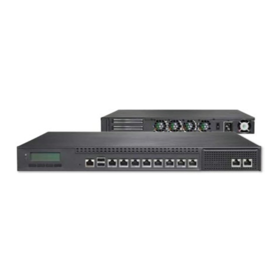
Page 8: Front Panel Features
Using suitable RJ-45 cable, you can connect FW-8760 System to a computer, or to any other piece of equipment that has an Ethernet connection; for example, a hub or a switch. Moreover, 3 pair (LAN1-LAN2, LAN3-LAN4, LAN5-LAN6) can be configured as LAN Bypass when failure events occur. -
Page 9: Rear Panel Features
Chapter 1 Introduction Rear Panel Features R1 Low Profile Expansion Slot R2 CPU fans 1-3 R3 Power-on Switch It is a switch to turn on or off the power. R4 AC Power-in socket The system requires a100-240 AC Power Supply.. R5 Power Supply Fan Network Application Platforms... -
Page 10: Chapter 2: Hardware Setup
Installing the Hard Disk The system can accommodate two Serial-ATA disks. Follow these steps to install a hard disk into the FW-8760: Installing the System Memory Unscrew the 4 screws on the hard disk tray to take out the hard disk tray from the system. -
Page 11: Installing A Compactflash Card
Chapter 2 Introduction CPU and the Heat Sink Installation The FW-8760 sever system is powered by the MB-8760 sever board, which comes with one ZIF type LGA775 CPU socket. Follow the procedures bellow for installing a CPU Remove the CPU socket cap. -
Page 12: Riser Card Installation
Chapter 2 Introduction Riser Card Installation Align the riser card with the PCI-E golden finger connector. Insert the card into the connector firmly. Fasten the screws to fix the card onto the board. Front Ethernet Module Installation To install the front Ethernet module, take off the front bracket first by unscrewing the threaded screws at the bottom of the case. -
Page 13: Din-Rail Rack Mounting
Chapter 2 Introduction Din-Rail Rack Mounting Inner Rail Installation To install the inner rail, separate it from the middle rail first. Follow the following procedures: Installation environment caution: Place the rails as shown below. The finger tab of extension safety lock should reveal. Elevated Operating Ambient - If installed in a closed or multi-unit rack assembly, the operating ambient Press the finger tab and pull the inner rail from the... -
Page 14: Outer Rail Installation
Chapter 2 Introduction Firmly tighten the Hex nut (4 on each side) on the Outer Rail Installation outer rail after adjusting the middle rail to its proper Use the following procedures to install the outer rail place.. Attach the rail bracket to the posts of the rack by using two screws (Rail bracket screws are not included, use the original manufacture’s rack bracket screws.) Do not completely tighten the screws;... -
Page 15: Chapter 3: Motherboard Information
Chapter 3 Motherboard Information Chapter 3: Motherboard Information Block Diagram The block diagram depicts the relationships among the interfaces or modules on the motherboard. Please refer to the following figure for your motherboard’s layout design. DDR3 1066/1333 Non-ECC Unbuffered Up to 16GB Lynnfield (Xeon) Maximum /Clarkdare... -
Page 16: Motherboard Layout
Chapter 3 Motherboard Information Motherboard Layout The motherboard layout shows the connectors and jumpers on the board. Refer to the following picture as a reference of the pin assignments and the internal connectors. AT Mode Power Button F A N 1 F A N 2 F A N 3 F A N 4 Connector A T X P o w e r C o n n e c t o r... -
Page 17: Jumper Settings
Chapter 3 Motherboard Information Jumper Settings Clear CMOS jumper (J6): It is for clearing the CMOS memory and system setup parameters by erasing the Fan Connectors(FAN1/FAN2/FAN3/FAN4): The 4-pin data stored in the CMOS RAM such as the system connector is for connecting the CPU fans. It comes passwords. - Page 18 Chapter 3 Motherboard Information M O D _ A U D I O _ RESERVED Mini-PCI Connector (PCIB1): The Mini-PCI slot enables a Mini-PCI expansion module to be connected to the AUDIO_GND GROUND board. If the processor which you choose is Lynnfield SYS_AUDIO_OUT SYS_AUDIO_IN SYS_AUDIO_OUT...
- Page 19 Chapter 3 Motherboard Information Note: To configure your Hard disk using the Power Button Connector(CONN2): It is for connecting integrated RAID feature, the Intel® Matrix the cable of the system power switch ( in ATX mode) Storage Manager software has to be installed on on the back panel.
- Page 20 Chapter 3 Motherboard Information VGA Interface (VGAA2) for OPMA: The VGAA2 Hardware or Software Reset Jumper(J19): The jumper can be adjusted to be in either hardware or software connector is only used when OPMA is connected. reset mode when the reset switch is pressed. The This 2X6 pin header is used to connect with the Mini-PCI graphic card by using a VGA cable (a 2x6 hardware reset will reboot the system without turning...
-
Page 21: Chapter 4: Bios Settings
Note: For the update version of the BIOS image, please visit Lanner’s support page at http://assist.lannerinc.com. Then select support center from the Main Menu and look under the folder for the desired product category. -
Page 22: Accessing The Bios Menu
Chapter 4 Bios Settings Accessing the BIOS menu When you are installing a motherboard or when the system prompts “Run Setup” during start-up, you will use the BIOS Setup program to configure the system, . This section explains how to configure your system using this program. -
Page 23: The Main Menu
Chapter 4 Bios Settings The Main Menu The main BIOS setup menu is the first screen that you can navigate. Each main BIOS setup menu option is described in this chapter. The Main BIOS setup menu screen has two main frames. The left frame displays all the options that can be configured. -
Page 24: Advanced Settings
Chapter 4 Bios Settings Advanced Settings Select the Advanced tab from the setup screen to enter the Advanced BIOS Setup screen. You can select any of the items in the left frame of the screen, such as SuperIO Configuration, to go to the sub menu for that item. You can display an Advanced BIOS Setup option by highlighting it using the <Arrow>... - Page 25 Chapter 4 Bios Settings Primary /Secondary IDE Master and Slave Sub Menu From the IDE Configuration screen, press <Enter> to access the sub menu for the primary/secondary IDE master and slave drives. Use this screen to select options for the Primary and Secondary IDE drives. Use the up and down <Arrow>...
- Page 26 Chapter 4 Bios Settings Option Description Disabled Set this value to prevent the BIOS from using Multi-Sector Transfer on the specified channel. The data to and from the device will occur one sector at a time. Auto Set this value to allow the BIOS to automatically detect device support for Multi-Sector Transfers on the specified channel.
- Page 27 Chapter 4 Bios Settings Option Description SWDMA1 Set this value to allow the BIOS to use Single Word DMA mode 1. It has a data transfer rate of 4.2 MBs. SWDMA2 Set this value to allow the BIOS to use Single Word DMA mode 2.
- Page 28 Chapter 4 Bios Settings 32Bit Data Transfer This option sets the 32-bit data transfer option. The Optimal and Fail-Safe default setting is Enabled. Option Description Disabled Set this value to prevent the BIOS from using 32-bit data transfers. Enabled Set this value to allow the BIOS to use 32-bit data transfers on support hard disk drives.
- Page 29 Chapter 4 Bios Settings Option Description Set this value to stop the AMIBIOS from searching the IDE bus for IDE disk drives in 10 seconds. Set this value to stop the AMIBIOS from searching the IDE bus for IDE disk drives in 15 seconds. Set this value to stop the AMIBIOS from searching the IDE bus for IDE disk drives in 20 seconds.
- Page 30 Chapter 4 Bios Settings Option Description Disabled Set this value to prevent the serial port from accessing any system resources. When this option is set to Disabled, the serial port physically becomes unavailable. 3F8/IRQ4 Set this value to allow the serial port to use 3F8 as its I/O port address and IRQ 4 for the interrupt address.
- Page 31 Chapter 4 Bios Settings Option Description 3E8/IRQ4 Set this value to allow the serial port to use 3E8 as its I/O port address and IRQ 4 for the interrupt address. If the system will not use a serial device, it is best to set this port to Disabled. 2E8/IRQ3 Set this value to allow the serial port to use 2E8 as its I/O port address and IRQ 3 for the interrupt...
- Page 32 Chapter 4 Bios Settings USB Configuration In this screen, you will be able to configure the USB controller. Network Application Platforms...
- Page 33 Chapter 4 Bios Settings USB Configuration Setting You can use this screen to select options for the USB Configuration. Use the up and down <Arrow> keys to select an item. Use the <Plus> and <Minus> keys to change the value of the selected option. The settings are described on the following pages.
- Page 34 Chapter 4 Bios Settings USB Mass Storage Device Configuration In this screen, you can configure the attached USB drive to be used as the system’s hard drive. USB Mass Storage Reset Delay This option sets the reset timing for the USB Mass Storage to be initialized.
- Page 35 Chapter 4 Bios Settings Hardware Health Configuration This menu shows the hardware monitor configuration settings. Select an item then press <Enter> to display the configuration options. Hardware Health Configuration It allows you to configure the smart fan feature. You can manually turn on the system fan with the Manual Mode or set the target system temperature at which the system fan will start running if the fan is not yet turned on with Thermal...
- Page 36 Chapter 4 Bios Settings Remote Access You can disable or enable the BIOS remote access feature here. Option Description Disabled Set this value to prevent the BIOS from using Remote Access. Serial Set the value for this option to Serial to allow the system to use the remote access feature.
- Page 37 Chapter 4 Bios Settings Serial Port Number Select the serial port you want to use for console redirection. You can set the value for this option to either COM1 or COM2. Option Description 115200 8,n,1 Set this value to allow you to select 115200 as the baud rate (transmitted bits per second) of the serial port.
- Page 38 Chapter 4 Bios Settings Lan Bypass Control In this screen, you can configure the Lan Bypass functionality. Lan Bypass for Port 1 and Port 2 You can activate or deactivate the Lan Bypass ports. For the description of the physical ports that are capable of the LAN Bypass function, refer to the Front Panel Feature in Chapter 1 Introduction.
- Page 39 Chapter 4 Bios Settings Restore on AC Power Loss This option lets you set the state of the system when it has just recovered from a power outage. Option Description Power Off When setting to Power Off, the system goes into “off state”...
-
Page 40: Boot Setup
Chapter 4 Bios Settings Boot Setup Select the Boot tab from the setup screen to enter the Boot BIOS Setup screen. You can select any of the items in the left frame of the screen, such as Boot Device Priority, to go to the sub menu for that item. - Page 41 Chapter 4 Bios Settings PS/2 Mouse Support It lets you enable or disable support for PS/2 mouse. Wait for ‘F1’ if error It determines whether the message, “Press F1 to continue” should be displayed when error occurs during start-up. Option Description Enabled When setting to enabled, the system dis-...
-
Page 42: Security Settings
Chapter 4 Bios Settings Security Settings Select Security Setup from the Setup main BIOS setup menu. All Security Setup options, such as password protection and virus protection, are described in this section. To access the sub menu for the following items, select the item and press <Enter>: Supervisor Password It indicates whether a supervisor password has been set. - Page 43 Chapter 4 Bios Settings Change Supervisor Password Select this option and press <Enter> to access the sub menu. You can use the sub menu to change the supervisor password. Change User Password Select this option and press <Enter> to access the sub menu.
-
Page 44: Exit Menu
Chapter 4 Bios Settings Exit Menu Select the Exit tab from the setup screen to enter the Exit BIOS Setup screen. You can display an Exit BIOS Setup option by highlighting it using the <Arrow> keys. All Exit BIOS Setup options are described in this section. The Exit BIOS Setup screen is at right. -
Page 45: Appendix A: Programming Watchdog Timer
Appendix A Programming Watchdog Timer Appendix A: Programming Watchdog Timer A watchdog timer is a piece of hardware that can be used to automatically detect system anomalies and reset the processor in case there are any problems. Generally speaking, a watchdog timer is based on a counter that counts down from an initial value to zero. -
Page 46: Appendix B: Setting Up Console Redirections
Remote Client System. Configure the following settings in the BIOS Setup menu for FW-8760: Please refer to the Remote Access Settings on Chapter 4 BIOS Settings. BIOS > Advanced > Remote Access Configuration >... -
Page 47: Appendix C: Programming The Lcm
Appendix C Programming the LCM Appendix C: want to show. =>Showdata1 Shown on Line1 Limited between 20 Programming the LCM Character =>Showdata2 Shown on Line2 Limited between 20 The LCD panel module (LCM) is designed to provide real- Character time operating status and configuration information for the system. -
Page 48: Appendix D: Programming Lan Bypass
There are typically two communication states for the bypass function, one is “Normal” state and another is “Bypass” state. Lanner provides three methods for enabling the LAN Bypass function: When the system powers off, it can be forced to enable the LAN Bypass function through the BIOS settings.(... -
Page 49: Appendix E: Driver Installation
Appendix E Driver Installation Appendix E: Select the “I accept the terms in the license agreement” and then click Next. Driver Installation LAN Adapters Driver Installation This section provides the instructions on how to install Intel® Gigabit LAN adapter drivers. Windows Operating systems To install the Intel®... -
Page 50: Linux
Appendix E Driver Installation VGA Driver Installation Linux Follow these instructions when installing the Intel® LAN This section provides the instructions on how to install controller base driver for the Red Hat® and Linux operating VGA adapter drivers. system. Windows Operating systems Insert the motherboard/system support CD to the optical drive and mount the optional drive in the Linux Restart the computer, and then log on with... -
Page 51: Appendix F: System Resource Assignment
IRQ 18 Intel(R) 5 Series/3400 Series Chipset This appendix contains the information about the address Family PCI Express Root mapping of the system resource on the FW-8760 system. IRQ 18 Intel(R) 82574L Gigabit Network Con- nection I/O Address Mapping... -
Page 52: Appendix G: Terms And Conditions
Appendix G Terms and Conditions Appendix G: RMA Service Terms and Conditions Requesting a RMA# To obtain a RMA number, simply fill out and fax the “RMA Request Form” to your supplier. Warranty Policy The customer is required to fill out the problem code as listed. - Page 53 Appendix G Terms and Conditions RMA Service Request Form When requesting RMA service, please fill out the following form. Without this form enclosed, your RMA cannot be processed. Reasons to Return: Repair(Please include failure details) RMA No: Testing Purpose Company: Contact Person: Phone No.
Need help?
Do you have a question about the FW-8760 and is the answer not in the manual?
Questions and answers