KE2 Therm Solutions EvaporatorEfficiency 20844 Quick Start Manual
Hide thumbs
Also See for EvaporatorEfficiency 20844:
- Quick start manual (21 pages) ,
- Quick start manual (4 pages) ,
- Quick start manual (20 pages)
Table of Contents
Advertisement
Quick Links
KE2 EvaporatorEfficiency
Condensed Quick Start Guide
Parts List
The following parts are included:
Kit #20178 with 120/208-240 VAC controller
Kit #20844
with 120/208-240 VAC controller
Kit #20631
with 120/208-240 VAC controller
Kit #20222
Beacon® I & II replacement
A
(1) KE2 Evaporator Efficiency controller
B
(1) high voltage safety shield
C
(3) 15' colored temperature sensors
D
(4) 90 degree quick disconnects
E
(5) self-tapping screws
(2) course thread screws &
F
(1) fine thread machine screw with lock washer
(1) KE2 Terminal Board with fuses
G
H
(1) KE2 Evap Navigation sticker
I
(2) 1/2" plastic knockout plugs
J
(4) wire ties (rated for low temp)
K
(1) Air sensor mount
L
(1) 5-position pluggable connector (for EEV)
(4) 3-position pluggable connectors (for power in, transducer and 3A
M
relays)
(9) 2-position pluggable connectors (for sensors and digital input, analog
N
output)
O
(1) 120 Voltage jumper
(1) 208-240V Voltage jumper (already installed on KE2 Evap)
P
(1) Split Bushing (for high voltage shield - not shown)
O
(1) EC Motor Relay (120V & 240 V) kit (not shown)
P
20844 KE2 Ultimate Install kit includes KE2 Mounting Box pn 20687
and 40' colored temperature sensors
20631 kit does not include temperature sensors
20222 Beacon® kit includes an extra temperature sensor, and pressure
transducer with cable.
*
To function properly, the controller requires a room temp sensor (T2Air - blue) and
a coil temp sensor (T3Coil - yellow) . KE2 Therm strongly recommends the third
sensor is used as 2nd coil temp sensor (T4Aux - green).
Introduction Mode
Applying power to the controller initializes it. It then automatically enters the In-
troduction Mode. The Introduction Mode consists of as little as 4 setpoints
that must be configured for the KE2 Evap to begin controlling the system.
Mechanical Valve TEV
Defined EEV
-
4 steps
5 steps
Room Temp
Room Temp
Defrost Type
Defrost Type
Valve Type
Valve Type
KE2 Smart Access
Refrigerant
KE2 Smart Access
MasterView Webpages
User Name and Password are required to modify the webpages.
User Name: ke2admin
The defaults are:
IMPORTANT: The User Name and Password should be changed from the de-
fault for security purposes.
© Copyright 2019 KE2 Therm Solutions, Inc., Washington, Missouri 63090
This reference should remain on site with the installed KE2 Evaporator Efficiency controller.
A
*
L
Custom EEV
8 steps
Room Temp
Defrost Type
Valve Type
Refrigerant
Motor Type
(Unipolar/Bipolar)
Motor Step Rate
Max Valve Steps
KE2 Smart Access
Password: ke2admin
B
C
D
E
F
I
J
K
M
N
Supplies List -
All accessories required for the controller to work are
supplied. However, truck stock items are required for the installation.
(2) Conduit to go between the controller and the evaporator
(2) Conduit connectors (straight or elbow as required)
(11) High voltage wires matched to the load of the heaters, fans, liquid line sole-
noid, alarm (if used), and the controller.
(8) Spade Connectors matched to gauge of high voltage wires
Wire labeling (numbers, colors, etc.)
Additional wire ties
18 gauge twisted shielded pair (if extending sensor wires)
Foam insulation if running wires outside the space.
Silicone (for sealing any box penetrations)
Popular Accessories -
The following parts are available separately:
Wire Harness- 10' pn 20736, 25' pn 20670, 40' pn 20737
Mounting Box pn 20687
Door Switch pn 20543
Buzzer & Light Combo pn 20973
Further information on accessories can be found in KE2 Condensed Catalog 411.
Complete Instructions
Please visit:
http://ke2therm.com/product/ke2-evaporatorefficiency/
and click the button Link to Literature.
— OR —
use this QR code.
KE2 Evaporator Efficiency Literature
Visit our YouTube channel for videos
on KE2 Evap installation and setup.
Video 046 How to Wire the KE2 Evap Controller
Video 033 How to Confirm the KE2 Evap is Wired Correctly
Video 068 How to Determine Proper Coil Sensor Location
Video 069 How to Properly Install a Coil Sensor
Video 032 Initial Defrost Sequence
Q.1.64
June 2019
NOTE: All sensors
can be used for any
purpose and are
*
interchangeable,
colors are for ease of
identification only.
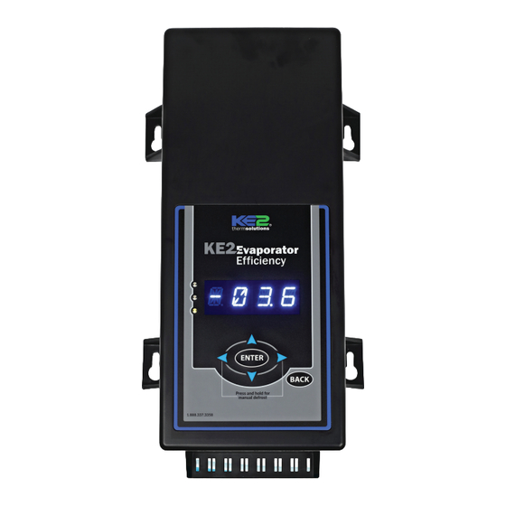
Controller Navigation
pn 21061 9-14
Lights:
Red - critical alarm (system not running)
Yellow - non-critical alarm (system running)
Green - compressor should be on
G
H
- compressor waiting on timer to start/stop
Moving through controller menus:
Left Arrow & Right Arrow
Use to move between Menus columns
Up Arrow & Down Arrow
ENTER
Scroll through Menu Parameters
BACK
Return to Main Menu:
BACK
Press BACK to return to the previous view.
Toggle beween
description & value :
ENTER
Press ENTER to go from parameter to value.
Press and hold ENTER for 3 seconds, when
Change settings:
ENTER
ENTER
display is blinking changes can be made.
Save changes:
ENTER
Press and hold ENTER for 3 seconds.
If you lose your place:
BACK
Press BACK 3 - 4 times
Menu Layout:
Enter
Variables
Alarms
Manual*
Password
(view only)
(view only)
ROOM TEMP
NO ALARM
ROOM TEMP
MANUAL CONTROL
FIRMWARE VERSION
EMAIL FAILURE
DERIVATIVE
CLEAR MD
* For manual defrost use MANUAL CONTROL
24-hour Emergency Support: 1.888.337.3358
www.ke2therm.com
O
P
youtube.com/ke2therm
Advertisement
Table of Contents

Related Manuals for KE2 Therm Solutions EvaporatorEfficiency 20844


Summary of Contents for KE2 Therm Solutions EvaporatorEfficiency 20844
- Page 1 IMPORTANT: The User Name and Password should be changed from the de- Video 069 How to Properly Install a Coil Sensor fault for security purposes. youtube.com/ke2therm Video 032 Initial Defrost Sequence © Copyright 2019 KE2 Therm Solutions, Inc., Washington, Missouri 63090...
- Page 2 Q.1.64 June 2019 Page 2 KE2 EvaporatorEfficiency Condensed Quick Start Guide Wiring Schematic - Controller New Installation BL/BK FROM CONTROLLER © Copyright 2019 KE2 Therm Solutions, Inc., Washington, Missouri 63090...
- Page 3 RATE, and MAX VALVE STEPS. menu. A second/third press will either return to the Main Menu, or to the room temperature reading. Step The fourth prompt is whether KE2 SMART ACCESS is ENABLED or © Copyright 2019 KE2 Therm Solutions, Inc., Washington, Missouri 63090...
- Page 4 3 seconds, when display 7 Only displayed when Run begins blinking changes Time Defrost is selected. can be made Save setting Press & hold ENTER for ENTER changes: 3 seconds to save change © Copyright 2019 KE2 Therm Solutions, Inc., Washington, Missouri 63090...
Need help?
Do you have a question about the EvaporatorEfficiency 20844 and is the answer not in the manual?
Questions and answers