Table of Contents
Advertisement
Quick Links
thermsolutions
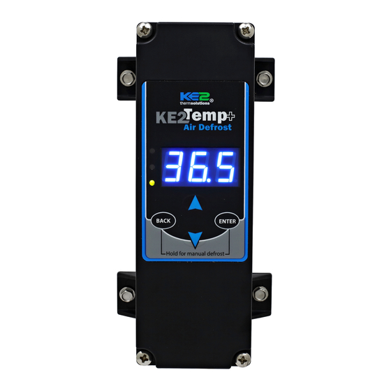
KE2 Temp + Air Defrost
For Medium Temperature Applications with Air Defrost
Installation Manual
A
Select Mounting Location
The KE2 Temp is designed for a wide range of applications; therefore
there are many potential installation locations. Breaking down the
installation location by application provides the most helpful reference.
Application
Locations
Evaporator cabinet
Under counter
Outside controlled space
Evaporator cabinet
Walk-in
Adjacent to entrance
Side-by-side
Above door
Remote Monitoring, Control, Alarm Notifications
The KE2 Temp includes RS-485 Modbus communications and can be
accessed remotely using the Alarms KE2 Edge Manager (KE2 EM). See
page 4 for additional details.
Service Call Saver -
Post Defrost Indicator
To eliminate unnecessary service calls, the KE2 Temp + Defrost alerts
the user when it is coming out of a defrost cycle using the onboard
display. The display alternates between dEF and the actual temperature
measured by the air sensor. This continues until the temperature has
reached setpoint, or for the amount of time set by dFt (Defrost Time)
whichever is shorter.
(pn 20611)
F
Programming
Press & hold ENTER button
to access setpoint menu
Use arrow buttons to
select function:
tS = Temperature Setpoint
diF =
CSH = Max Compressor
Starts/ Hour
dPd = Defrost Per Day
dFt = Defrost Time
B
LAO =
tAd = Temp Alarm Delay
Adr = Mod Bus Address
Unt = Units for temp display
Press ENTER & use arrows
to change value
Press & hold ENTER button
Alarms
When amber LED is lit:
SSA = Shorted Sensor Alarm
OSA = Open Sensor Alarm
HtA = High Temp Alarm
C
D
LtA = Low Temp Alarm
pn 20679
G
E
This reference should remain on site with the
installed KE2 Temp + Air Defrost controller.
Parts List
The following parts are included in the KE2 Temp + Defrost kit:
(1) KE2 Temp + Defrost controller
A
(1) temperature sensor - 45"
B
(4) self-tapping mounting screws
C
(1) liquid tight cord grip
D
(1) sensor ziptie
E
(1) programming sticker
F
G
(2) screws for high voltage shield
Supplies List
All of the accessories required for the controller to work are supplied,
however, standard truck stock items are required to install the controller.
06/14
A list is provided below:
conduit to go between the controller & evaporator
(2) conduit connectors (straight or elbow as required)
(4) high voltage wires matched to the load of the liquid line solenoid/
compressor and the controller.
wire labeling (numbers, colors, etc.)
additional wire ties
18 gauge twisted shielded pair (if extending sensor wires)
foam insulation (if running wires outside the space)
silicone (for sealing any box penetrations)
Cat5e cable (if setting up communications)
Walk-in
Wine Cabinet
© Copyright 2021 KE2 Therm Solutions, Inc., Washington, Missouri 63090
Q.3.20 (Q.1.20) May 2021
Under Counter
Commercial
Advertisement
Table of Contents

Related Manuals for KE2 Therm Solutions Temp + Air Defrost


Summary of Contents for KE2 Therm Solutions Temp + Air Defrost
- Page 1 The display alternates between dEF and the actual temperature measured by the air sensor. This continues until the temperature has reached setpoint, or for the amount of time set by dFt (Defrost Time) whichever is shorter. © Copyright 2021 KE2 Therm Solutions, Inc., Washington, Missouri 63090...
-
Page 2: Wiring The Controller
The controller will be breaking one leg of power to the LLS. èSTEP 6 is continued on the next page © Copyright 2021 KE2 Therm Solutions, Inc., Washington, Missouri 63090... -
Page 3: Low Voltage Connections
Temperature sensor Liquid tight cord grip - snaps into conduit opening at the top of the controller. © Copyright 2021 KE2 Therm Solutions, Inc., Washington, Missouri 63090... -
Page 4: Communications Wiring
Connect wirelessly to the KE2-EM Network Webpage View From the Webpage you can monitor temperatures, relay status and alarms, as well as make changes to setpoints, and manually control the system. © Copyright 2021 KE2 Therm Solutions, Inc., Washington, Missouri 63090... -
Page 5: Programming The Controller
For Medium Temperature Applications with Air Defrost Installation Manual Programming the Controller Many applications of the KE2 Temp + Air Defrost can use the KE2 Temp + Air Defrost Basic Navigation controller’s preset defrosts per day. This automatically spaces the Understanding the KE2 Temp + Air Defrost’s menu structure will... - Page 6 Units for temp display *Selecting fewer than 5 compressor starts per hour results in the starts per hour feature being turned off. The compressor will then function on temperature only. © Copyright 2021 KE2 Therm Solutions, Inc., Washington, Missouri 63090...
- Page 7 After the time is set, press and hold Press the button to save settings, BACK button for 3 seconds, and return to the main screen (room ENTER until tod is displayed temp will be displayed). © Copyright 2021 KE2 Therm Solutions, Inc., Washington, Missouri 63090...
-
Page 8: Dimensions - Inches
Neutral (L2) LLS (Liquid Line Solenoid) or COMPRESSOR CONTACTOR © Copyright 2021 KE2 Therm Solutions, Washington, Missouri 63090 KE2 Therm Solutions Q.3.20 (Q.1.20) May 2021 supersedes Q.3.20 (Q.1.20) December 2020 and all prior publications 12 Chamber Dr. . Washington, MO 63090...
Need help?
Do you have a question about the Temp + Air Defrost and is the answer not in the manual?
Questions and answers