KE2 Therm Solutions 20844 Quick Start Manual
Evaporator efficiency controller
Hide thumbs
Also See for 20844:
- Quick start manual (4 pages) ,
- Quick start manual (4 pages) ,
- Quick start manual (20 pages)
Table of Contents
Advertisement
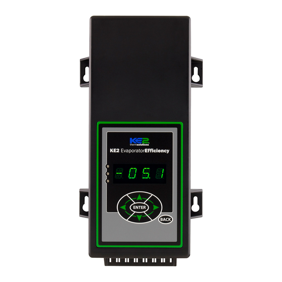
KE2 EvaporatorEfficiency
Quick Start Guide
This reference should remain on site with the installed KE2 Evaporator Efficiency controller.
Parts List
The following parts are included in the
KE2 Evaporator Efficiency (KE2 Evap) controller kits:
Kit #20178 with 120/208-240 VAC controller
Kit #20844
with 120/208-240 VAC controller
Kit #20631
with 120/208-240 VAC controller
Kit #20222
Beacon® I & II replacement controller
(1) KE2 Evaporator Efficiency controller
A
(1) high voltage safety shield
B
(3) 15' colored temperature sensors
C
(4) 90 degree quick disconnects
D
(5) self-tapping screws
E
(2) course thread screws (1) fine thread machine screw with
F
lock washer
(1) KE2 Terminal Board with fuses
G
(1) KE2 Evap Navigation sticker
H
(2) 1/2" plastic knockout plugs
I
(4) wire ties (rated for low temp)
J
(1) Air sensor mount
K
(1) 5-position pluggable connector (for EEV)
L
(4) 3-position pluggable connectors (for power in, transducer
M
and 3A relay)
(9) 2-position pluggable connectors (for sensors and digital
N
input, analog output)
O
(1) 120 Voltage jumper
P
(1) 208-240V Voltage jumper (already installed on KE2 Evap)
20844 KE2 Ultimate Install kit includes KE2 Mounting Box pn 20687 and 40'
colored temperature sensors
20631 kit does not include temperature sensors
20222 Beacon® kit includes an extra temperature sensor, and pressure
transducer with cable.
© Copyright 2017 KE2 Therm Solutions, Inc., Washington, Missouri 63090
A
B
D
E
I
K
L
M
C
Controller Navigation
Lights:
Red - critical alarm (system not running)
Yellow - non-critical alarm (system running)
Green - compressor should be on
F
G
H
- compressor waiting on timer to start/stop
Moving through controller menus:
Left Arrow & Right Arrow
Use to move between Menus columns
ENTER
Up Arrow & Down Arrow
Scroll through Menu Parameters
BACK
Return to Main Menu:
BACK
Press BACK to return to the previous view.
Toggle beween
ENTER
Press ENTER to go from parameter to value.
description & value :
Change settings:
Press and hold ENTER for 3 seconds, when
ENTER
ENTER
display is blinking changes can be made.
Save changes:
ENTER
Press and hold ENTER for 3 seconds.
If you lose your place:
BACK
Press BACK 3 - 4 times
Menu Layout:
J
Variables
Alarms
Setpoints
(view only)
(view only)
ROOM TEMP
NO ALARM
ROOM TEMP
FIRMWARE VERSION
EMAIL FAILURE
DERIVATIVE
24-hour Emergency Support: 1.888.337.3358
O
N
Supplies List
The KE2 Evap is supplied with all of the accessories required for the con-
troller to work, however, standard truck stock items will also be required
to install the controller. A list of items is provided.
Conduit to go between the controller and the evaporator
(2) Conduit connectors (straight or elbow as required)
(11) High voltage wires matched to the load of the heaters, fans, liquid
line solenoid, alarm (if used), and the controller.
(8) Spade Connectors matched to gauge of high voltage wires
Wire labeling (numbers, colors, etc.)
Additional wire ties
18 gauge twisted shielded pair (if extending sensor wires)
Foam insulation if running wires outside the space.
Silicone (for sealing any box penetrations)
Popular Accessories
The following parts are available separately:
Wire Harness- 10' pn 20736, 25' pn 20670, 40' pn 20737
Mounting Box pn 20687
Door Switch pn 20543
Buzzer pn 20972
Buzzer & Light Combo pn 20973
Further information on accessories can be found in KE2 Condensed Catalog 411.
Visit our YouTube channel for videos
on KE2 Evap installation and setup.
Video 046 How to Wire the KE2 Evap Controller
Video 033 How to Confirm the KE2 Evap is Wired Correctly
Video 068 How to Determine Proper Coil Sensor Location
Video 069 How to Properly Install a Coil Sensor
Video 032 Initial Defrost Sequence: KE2 Evap & KE2 Adaptive Control
Video 012 How to Navigate the KE2 Evap Controller
Video 020 KE2 Evap Scrolling Text - Initiate Manual Defrost
Video 017 KE2 Evap Scrolling Text - Change Room Temp Setpoint
Video 040 Configure the KE2 Evap for a Door Switch from the Front Panel
youtube.com/ke2therm
November 2017
NOTE: All sensors can be
used for any purpose and
are interchangeable,
colors are for ease of
identification only.
pn 21061 9-14
Enter
Manual*
Password
MANUAL CONTROL
CLEAR MD
* For manual defrost use MANUAL CONTROL
www.ke2therm.com
P
Q.1.3
Advertisement
Table of Contents

Related Manuals for KE2 Therm Solutions 20844


Summary of Contents for KE2 Therm Solutions 20844
- Page 1 Video 017 KE2 Evap Scrolling Text - Change Room Temp Setpoint Video 040 Configure the KE2 Evap for a Door Switch from the Front Panel 20844 KE2 Ultimate Install kit includes KE2 Mounting Box pn 20687 and 40’ colored temperature sensors youtube.com/ke2therm...
- Page 2 (must be within operating range -40°F to 140°F (-40°C to 60°C) On the wall thermsolutions KE2 EvaporatorEfficiency ENTER BACK At the entrance KE2 EvaporatorEfficiency thermsolutions ENTER BACK © Copyright 2017 KE2 Therm Solutions, Inc., Washington, Missouri 63090...
-
Page 3: Wiring The Controller
3 position connector. Controller will illuminate display when 120V is applied with 208-240V Defrost NO NC Relay selected, however, controller will not function properly. 120V 208-240V Solenoid Relay © Copyright 2017 KE2 Therm Solutions, Inc., Washington, Missouri 63090 Auxiliary Relay... - Page 4 Locate the remaining 2 female spade connectors in parts kit. Crimp on the female connectors. Plug the connectors into COM and NO positions of the Defrost Relay. Confirm combined heater load is not over 20 amps. © Copyright 2017 KE2 Therm Solutions, Inc., Washington, Missouri 63090...
-
Page 5: Auxiliary Relay
Verify power is no longer present using a multimeter. Evaporator wiring Now that the conduit is prepared, it can be connected to the evaporator. Locate the proper sized knockout and carefully remove knockout. Connect conduit to the evaporator © Copyright 2017 KE2 Therm Solutions, Inc., Washington, Missouri 63090... - Page 6 Power Input nal board. BK/OR Ground 208-240 WT/R Relay Voltage Jumper NO NC 208-240 Default OR NEUTRAL HEATERS Defrost NO NC Relay thermsolutions ® P/N 20996 Solenoid Relay Auxiliary Relay © Copyright 2017 KE2 Therm Solutions, Inc., Washington, Missouri 63090...
- Page 7 Y/BK Power Input BK/OR Ground 208-240 WT/R Relay Voltage Jumper NO NC 208-240 Default OR NEUTRAL HEATERS Defrost NO NC Relay thermsolutions ® P/N 20996 Solenoid Relay Auxiliary Relay © Copyright 2017 KE2 Therm Solutions, Inc., Washington, Missouri 63090...
- Page 8 Q.1.3 November 2017 Page 8 KE2 EvaporatorEfficiency Quick Start Guide Wiring Schematic - Controller New Installation BL/BK FROM CONTROLLER © Copyright 2017 KE2 Therm Solutions, Inc., Washington, Missouri 63090...
- Page 9 Q.1.3 November 2017 Page 9 KE2 EvaporatorEfficiency Quick Start Guide Wiring Schematic - Controller with KE2 Contactor Box © Copyright 2017 KE2 Therm Solutions, Inc., Washington, Missouri 63090...
- Page 10 Item I from Parts List on page 1 As with any wiring installation, it is appropriate to leave a service loop. Enough wire should be left to move the sensor to the opposite end of the evaporator. © Copyright 2017 KE2 Therm Solutions, Inc., Washington, Missouri 63090...
- Page 11 Thermistor close to the defrost heat source. In these instances, the method shown in Figure 29 can be used. © Copyright 2017 KE2 Therm Solutions, Inc., Washington, Missouri 63090...
-
Page 12: Controller Mounting
Locate the 4 stainless steel mounting screws in the accessories kit Install the 4 screws Place the controller on the screws and tighten down the screws. Final Step Leave installation instructions onsite for future service. © Copyright 2017 KE2 Therm Solutions, Inc., Washington, Missouri 63090... -
Page 13: Specifications
Pressure Transducer Part Number black 20222 Beacon brown Wiring Detail Beacon® II green replacement white controller green yellow/black required. signal Pressure Transducer ground Temperature Sensors (4) Beacon® II blue white black © Copyright 2017 KE2 Therm Solutions, Inc., Washington, Missouri 63090... - Page 14 6 The Setpoint parameters shown TEMP UNITS in BOLD ITALIC are active for AIR TEMP DIFF bonded controllers only. EXTREME TEMP DIFF PROPORTIONAL 7 Only displayed when Run Time INTEGRAL Defrost is selected. DERIVATIVE © Copyright 2017 KE2 Therm Solutions, Inc., Washington, Missouri 63090...
-
Page 15: User Interface
ENTER These are the only setpoints required to begin controlling the system. For setup with multi-evaporator applications see bulletins Q.5.10 and Q.1.32 © Copyright 2017 KE2 Therm Solutions, Inc., Washington, Missouri 63090... - Page 16 Connect the KE2 Evap to the customer’s network. ® thermsolutions Evaporator Efficiency CAT5 Ethernet Cable ENTER BACK Press and hold for Link/ACT manual defrost 24-hour POWER Emergency Technical Support 1.888.337.3358 100/1000Mbps Customer Network © Copyright 2017 KE2 Therm Solutions, Inc., Washington, Missouri 63090...
- Page 17 For additional information on KE2 Smart Access, visit IP-10.10.52.19 IP-10.10.52.19 http://ke2therm.com/productliteratureevap4.html, and see bulletins A.1.76 The KE2 Evap v4.0 with KE2 Smart 00:04:A3:14:E5:92 00:04:A3:14:E5:92 Access and q.1.34 KE2 Smart Access Setup and Custom- izing. © Copyright 2017 KE2 Therm Solutions, Inc., Washington, Missouri 63090...
-
Page 18: Setpoints Menu
A coefficient to the valve control algorithm that increases valve responsiveness INTEGRAL A coefficient to the valve control algorithm that increases valve responsiveness DERIVATIVE Should not be adjusted unless instructed by KE2 Therm technical support © Copyright 2017 KE2 Therm Solutions, Inc., Washington, Missouri 63090... - Page 19 Q.1.3 November 2017 Page 19 KE2 EvaporatorEfficiency Quick Start Guide Range Default Parameter Name -50°F to 90°F -10°F ROOM TEMP ELEC, AIR, HOT GAS COMP ON, HOT GAS COMP OFF ELEC DEFROST TYPE MECHANICAL, KE2 RSV, KE2 HSV, SER/SEI 1 TO 20, SER B TO L, SEI 30, SEI 50, SEH, ETS12 TO 50, MECHANICAL VALVE TYPE ETS100, ETS250/400, CAREL, CUSTOM;...
-
Page 20: Manual Menu
Controller cannot read or write to the flash memory. Contact KE2 Therm. KE2 Therm Solutions 12 Chamber Drive . Washington, MO 63090 © Copyright 2017 KE2 Therm Solutions, Inc., Washington, Missouri 63090 1.888.337.3358 . www.ke2therm.com Q.1.3 November 2017 supersedes Q.1.3 March2017 and all prior publications.
Need help?
Do you have a question about the 20844 and is the answer not in the manual?
Questions and answers