Table of Contents
Advertisement
Quick Links
KE2 Temp + Defrost
For Medium Temperature Applications with Air Defrost
Installation Manual
This reference should remain on site with the installed KE2 Temp + Defrost controller.
A
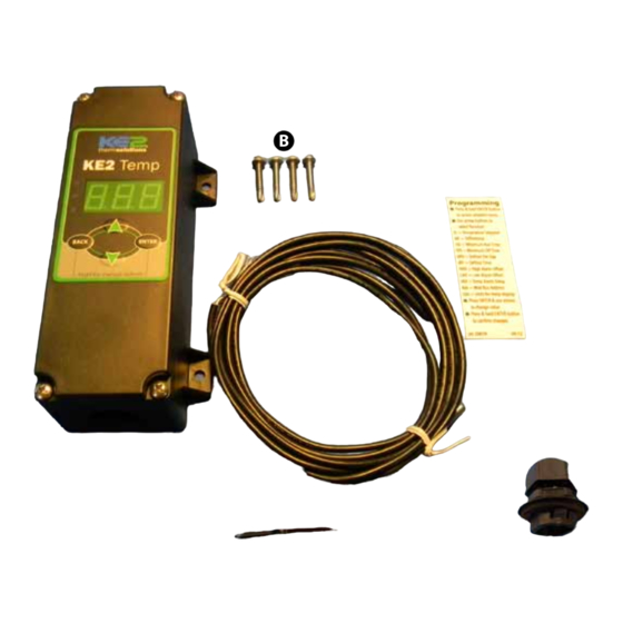
What's in the Kit - Parts List
The following parts are included in the
KE2 Temp + Defrost kit:
(1) KE2 Temp + Defrost controller
A
(4) mounting screws
B
(1) temperature sensor - 10'
C
D
(1) sensor ziptie
E
(1) programming sticker
F
(1) liquid tight cord grip
© Copyright 2014 KE2 Therm Solutions, Inc., Washington, Missouri 63090
(pn 20611)
B
C
D
Supplies List
The KE2 Temp + Defrost is supplied with all of the accessories re-
quired for the controller to work, however, standard truck stock items
will also be required to install the controller. To simplify the installa-
tion, a list of items has been provided.
conduit to go between the controller and the evaporator
(2) conduit connectors (straight or elbow as required)
(4) high voltage wires matched to the load of the liquid
line solenoid/compressor and the controller.
wire labeling (numbers, colors, etc.)
additional wire ties
18 gauge twisted shielded pair (if extending sensor wires/
adding communication)
foam insulation if running wires outside the space.
silicone (for sealing any box penetrations)
February 2014
E
F
Q.1.20
Advertisement
Table of Contents

Related Manuals for KE2 Therm Solutions temp + defrost


Summary of Contents for KE2 Therm Solutions temp + defrost
- Page 1 (pn 20611) For Medium Temperature Applications with Air Defrost Installation Manual This reference should remain on site with the installed KE2 Temp + Defrost controller. Supplies List What’s in the Kit - Parts List The KE2 Temp + Defrost is supplied with all of the accessories re-...
- Page 2 The display is connected to the lower board by a short ribbon cable. Caution: The board may be damaged if exces- sive force is used when removing the cover. © Copyright 2014 KE2 Therm Solutions, Inc., Washington, Missouri 63090...
- Page 3 With the high voltage cover removed, the two screw terminal connectors can be seen. The 2-position connector is the controller’s power supply. The voltage selector switch should be positioned to match the voltage supplied. © Copyright 2014 KE2 Therm Solutions, Inc., Washington, Missouri 63090...
- Page 4 (1) Relay Single Pole Double Throw Resistive Horsepower 1 hp 2 hp 1/4 hp 1/2 hp Pilot Duty 800VA 720VA 290VA 360VA Replace high voltage shield after wiring is completed. © Copyright 2014 KE2 Therm Solutions, Inc., Washington, Missouri 63090...
-
Page 5: Low Voltage Connections
Communication The KE2 Temp includes RS-485 Modbus commu- nication. RS-485 communication should be con- nected to the A, B, and Sh (shield) connections. © Copyright 2014 KE2 Therm Solutions, Inc., Washington, Missouri 63090... -
Page 6: Programming The Controller
OSA = Open Sensor Alarm HtA = High Temperature Alarm LtA = Low Temperature Alarm For further explanation of Setpoints please see the KE2 Temp + Defrost Operation Manual, O.1.3. © Copyright 2014 KE2 Therm Solutions, Inc., Washington, Missouri 63090... -
Page 7: Advanced Setpoints
Units for temp display *Selecting fewer than 5 compressor starts per hour results in the starts per hour feature being turned off. The compressor will then function on temperature only. © Copyright 2014 KE2 Therm Solutions, Inc., Washington, Missouri 63090... -
Page 8: Wiring Diagram
2.79 2.30 End View 2.14 KE2 Therm Solutions © Copyright 2014 KE2 Therm Solutions, Inc., Washington, Missouri 63090 Q.1.20 February 2014 supersedes bulletin Q.1.20 February 2013 and all prior publications. 209 Lange Dr. . Washington, MO 63090 1-888-337-3358 . www.ke2therm.com...
Need help?
Do you have a question about the temp + defrost and is the answer not in the manual?
Questions and answers