Table of Contents
Advertisement
Quick Links
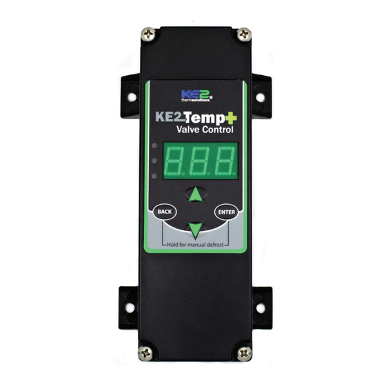
KE2 Temp + Valve Control
For Medium Temperature Applications with Air Defrost
Installation Manual
This reference should remain on site with the installed KE2 Temp + Valve controller.
What's in the Kit - Parts List
The following are included in the KE2 Temp + Valve kit, pn 21301:
A
(1) KE2 Temp + Valve controller (pn21393 - controller only)
B
(1)10' pressure transducer
C
(1) temperature sensor - 45"
D
(1) temperature sensor - 10'
E
(4) self-tapping mounting screws
F
(1) sensor ziptie
G
(1) screwdriver
H
(2) screws for high voltage shield
Supplies List
Standard truck stock items are required to install the
controller. A list is provided below
conduit to go between the controller & evaporator
(2) conduit connectors (straight or elbow as required)
(4) high voltage wires matched to the load of the
liquid line solenoid/compressor and the controller.
wire labeling (numbers, colors, etc.)
additional wire ties
18 gauge twisted shielded pair (if extending sensor
wires/adding communication)
foam insulation (if running wires outside the space)
silicone (for sealing any box penetrations)
Select Mounting Location
The KE2 Temp + Valve is designed for a wide range of applications, with
many potential installation locations. Breaking down the installation lo-
cation, by application, provides the most helpful reference.
Application
Locations
Evaporator cabinet
Under counter
Outside controlled space
Evaporator cabinet
Walk-in
Adjacent to entrance
Side-by-side
Above door
Remote Monitoring, Control, Alarm Notifications
The Temp + Valve includes RS-485 Modbus communications, and can
now be accessed remotely using the KE2 Local Area Dashboard and
Alarms (KE2 LDA). See page 4 for additional details.
Service Call Saver -
Post Defrost Indicator
To eliminate unnecessary service calls, the KE2 Temp + Valve alerts the
user when it is coming out of a defrost cycle using the onboard dis-
play. The display alternates between dEF and the actual temperature
measured by the air sensor. This continues until the temperature has
reached setpoint, or for the amount of time set by dFt (Defrost Time)
whichever is shorter.
© Copyright 2017 KE2 Therm Solutions, Inc., Washington, Missouri 63090
(kit pn 21301)
A
B
E
F
G
Walk-in
Wine Cabinet
April 2017
C
D
H
Under Counter
Commercial
Q.3.49
Advertisement
Table of Contents

Related Manuals for KE2 Therm Solutions Temp+Valve


Summary of Contents for KE2 Therm Solutions Temp+Valve
- Page 1 The display alternates between dEF and the actual temperature measured by the air sensor. This continues until the temperature has reached setpoint, or for the amount of time set by dFt (Defrost Time) whichever is shorter. © Copyright 2017 KE2 Therm Solutions, Inc., Washington, Missouri 63090...
-
Page 2: Wiring The Controller
Proper wiring practices must be followed. Local wiring codes take Outputs: 120V 240V precedence over any information in this bulletin. (1) Relay Single Pole Replace high voltage shield after wiring is completed. Double Throw Pilot Duty © Copyright 2017 KE2 Therm Solutions, Inc., Washington, Missouri 63090... -
Page 3: Low Voltage Connections
The KE2 Temp + Valve includes RS-485 Modbus communications, and can now be accessed remotely using the KE2 Local Area Dashboard and Alarms (KE2 LDA). See page 4 for further details. © Copyright 2017 KE2 Therm Solutions, Inc., Washington, Missouri 63090... - Page 4 KE2 LDA to KE2 Smart Access Video 061 What information is on the KE2 LDA’s Dashboard and Manage- ment Console Video 062 Communication Made Easy with KE2 Smart Access youtube.com/ke2therm © Copyright 2017 KE2 Therm Solutions, Inc., Washington, Missouri 63090...
-
Page 5: Programming The Controller
& to adjust, and Only shown if input is Manual press BACK to exit. pressure for EEPR or Menu EHGBP Only shown if in SH or SHt and tt selected. © Copyright 2017 KE2 Therm Solutions, Inc., Washington, Missouri 63090... - Page 6 LPC set point without satisfying minimum off time. If this occurs 4 times Amber SCC sCC while in Off mode, can be over multiple cycles, set alarm; Clear alarm if pressure does not go above LPC setpoint through minimum off time. © Copyright 2017 KE2 Therm Solutions, Inc., Washington, Missouri 63090...
- Page 7 *Selecting fewer than 5 compressor starts per hour results in the starts per hour feature being turned off. The compressor will then function on temperature only. ** Selecting CUS (custom) unlocks additional Setpoints. © Copyright 2017 KE2 Therm Solutions, Inc., Washington, Missouri 63090...
- Page 8 *Selecting fewer than 5 compressor starts per hour results in the starts per hour feature being turned off. The compressor will then function on temperature only. ** Selecting CUS (custom) unlocks additional Setpoints. © Copyright 2017 KE2 Therm Solutions, Inc., Washington, Missouri 63090...
- Page 9 *Selecting fewer than 5 compressor starts per hour results in the starts per hour feature being turned off. The compressor will then function on temperature only. ** Selecting CUS (custom) unlocks additional Setpoints. © Copyright 2017 KE2 Therm Solutions, Inc., Washington, Missouri 63090...
- Page 10 *Selecting fewer than 5 compressor starts per hour results in the starts per hour feature being turned off. The compressor will then function on temperature only. ** Selecting CUS (custom) unlocks additional Setpoints. © Copyright 2017 KE2 Therm Solutions, Inc., Washington, Missouri 63090...
- Page 11 *Selecting fewer than 5 compressor starts per hour results in the starts per hour feature being turned off. The compressor will then function on temperature only. ** Selecting CUS (custom) unlocks additional Setpoints. © Copyright 2017 KE2 Therm Solutions, Inc., Washington, Missouri 63090...
- Page 12 *Selecting fewer than 5 compressor starts per hour results in the starts per hour feature being turned off. The compressor will then function on temperature only. ** Selecting CUS (custom) unlocks additional Setpoints. © Copyright 2017 KE2 Therm Solutions, Inc., Washington, Missouri 63090...
- Page 13 Pressure is below Low Pressure Cutout (LPC) after 3 consecutive attempts to start the system Low Pressure Cut Out Setpoint Pressure at which controller de-energizes the Compressor/Liquid Line Solenoid relay (COr) © Copyright 2017 KE2 Therm Solutions, Inc., Washington, Missouri 63090...
- Page 14 Option for InP (input type) when HGB or EPR are selected for CtL (control type) Motor Type Setpoint When CUS (custom) valve is selected, the type of valve motor: Uni (unipolar), bi (bipolar) Temp Units Setpoint Fahrenheit (FAH) or Celsius (CEL) © Copyright 2017 KE2 Therm Solutions, Inc., Washington, Missouri 63090...
-
Page 15: Indicator Lights
After the time is set, press and hold Press the button to save set- button for 3 seconds, until tings, and return to the main screen tOd is displayed (room temp will be displayed). © Copyright 2017 KE2 Therm Solutions, Inc., Washington, Missouri 63090... -
Page 16: Wiring Diagram
2.79 Relay 115/230 2.30 End View 2.14 120 (208 - 240)/1/60 CONTROLLER POWER COMP SUPPLY Neutral (L2) © Copyright 2017 KE2 Therm Solutions, Inc., Washington, Missouri 63090 KE2 Therm Solutions 12 Chamber Drive . Washington, MO 63090 1-888-337-3358 . www.ke2therm.com...
Need help?
Do you have a question about the Temp+Valve and is the answer not in the manual?
Questions and answers