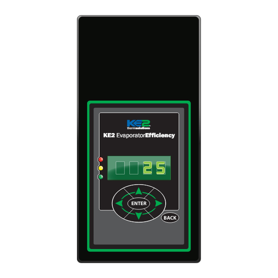
KE2 Therm Solutions Evaporator Efficiency Installation Instructions Manual
Hide thumbs
Also See for Evaporator Efficiency:
- Installation manual (20 pages) ,
- Quick start manual (20 pages) ,
- Installation instructions manual (16 pages)
Table of Contents
Advertisement
Advertisement
Table of Contents

Subscribe to Our Youtube Channel
Summary of Contents for KE2 Therm Solutions Evaporator Efficiency
- Page 1 Installation N.1.1 August 2011 KE2 EvaporatorEfficiency Installation Instructions thermsolutions thermsolutions thermsolutions KE2 EvaporatorEfficiency ENTER BACK KE2 Therm Solutions Providing Advanced Energy Saving Technology for Commercial Refrigeration and AC Systems.
-
Page 2: Table Of Contents
Figure 4: Coil Sensor Placement ... . . Page 5 - OR - Figure 5: Evaporator Efficiency Diagram ..Page 6 Kit #20222* with Beacon II Figure 6: Typical Piping Diagram - Hot Gas . -
Page 3: Location
6 inches from the coil surface. thermsolutions KE2 EvaporatorEfficiency Figure 2 - Return Air Sensor Placement ENTER BACK >6” At the entrance Sensor KE2 EvaporatorEfficiency thermsolutions ENTER BACK Return Air Copyright 2011 KE2 Therm Solutions, Washington, Missouri 63090... -
Page 4: Figure 3: Proper Sensor Location
When the voltage exceeds the allowed amount, the MOVs short to ground, protecting the circuitry. For additional protection, the board has a replaceable BK/MDL-1/4 fuse in line. The grey plug is accessible without removing the metal shield in the fuse Copyright 2011 KE2 Therm Solutions, Washington, Missouri 63090... -
Page 5: Figure 4: Coil Sensor Placement
The remaining leg, (L2), should be connected to one lead on the solenoid/com- pressor contactor. The remaining lead, should be connected to the normally open (NO) position on the terminal. Copyright 2011 KE2 Therm Solutions, Washington, Missouri 63090... - Page 6 Installation N.1.1 August 2011 Page 6 KE2 EvaporatorEfficiency Installation Instructions thermsolutions Figure 5 - KE2 Evaporator Efficiency - Diagram (back view) Fuse Bk/MDL-1/4 Time Delay Voltage Jumper Power In line Power In ground neutral Fan Relay (10 amp) NO NC...
-
Page 7: Figure 6: Typical Piping Diagram - Hot Gas
KE2 Evap Additional circuits thermsolutions KE2 EvaporatorEfficiency ENTER BACK Note: Controllers must be bonded and Multi Evaporator Defrost (MEVD) setpoint must be set to Independent (INDP) Piping shown for illustration purposes only. Copyright 2011 KE2 Therm Solutions, Washington, Missouri 63090... - Page 8 EEV - Electric Expansion Valve D1 - Digital Input 1 D2 - Digital Input 2 D3 - Digital Input 3 - - - By others All field wiring must conform to local codes Copyright 2011 KE2 Therm Solutions, Washington, Missouri 63090...
- Page 9 Installation N.1.1 August 2011 Page 9 KE2 EvaporatorEfficiency Installation Instructions thermsolutions Copyright 2011 KE2 Therm Solutions, Washington, Missouri 63090...
-
Page 10: Dimensions
Installation N.1.1 August 2011 Page 10 KE2 EvaporatorEfficiency Installation Instructions thermsolutions Figure 9 - KE2 Evaporator Efficiency - Dimensions (front view) Dimensions - Inches Depth 2.45” Pressure Transducer 5.75 0.95 0.67 2.03 1.40 2.03 female 1/4” SAE with 11.75 6.75... -
Page 11: Mounting The Controller
Menu or to the room temperature reading. These are the only setpoints required to begin controlling the system, when applied on a single evaporator with a mechanical valve, See Table 1 . Copyright 2011 KE2 Therm Solutions, Washington, Missouri 63090... - Page 12 Calibrate - Return Air Temperature Sensor Calibrate - Coil Temperature Sensor Calibrate - Auxiliary Temperature Sensor Temperature Units Valve Type Motor Type Step Rate Maximum Steps for Full Stroke Refrigerant Type Superheat Setpoint Copyright 2011 KE2 Therm Solutions, Washington, Missouri 63090...
-
Page 13: Variables Menu
Manually energize or de-energize defrost heater relay On/Off/Auto Auto Manual Relay Position MFAN Manually energize or de-energize evaporator fan relay On/Off/Auto Auto DHCP Ethernet Connection DHCP DHCP enabled Yes/No Factory Settings FACT Return controller to factory settings Copyright 2011 KE2 Therm Solutions, Washington, Missouri 63090... - Page 14 Installation N.1.1 August 2011 Page 14 KE2 EvaporatorEfficiency Installation Instructions thermsolutions Setpoints Menu - STPT Parameter Name Abbreviation Description Room Temp Setpoint RMSP If TAIR goes below this setpoint, go into OFF mode Air Temperature Differential ADIF If TAIR goes above this setpoint, go into REFR mode (must be greater than or equal to Cut Out Set Point) Minimum Run Time MRTM After entering REFR mode, the minimum amount of time that controller must stay in REFR mode...
-
Page 15: Setpoint Menu
Installation N.1.1 August 2011 Page 15 KE2 EvaporatorEfficiency Installation Instructions thermsolutions Table 4 - Defrost Defaults Setpoint Electric Hot Gas Range Default Current -50 to 90 degrees F -10 degrees F Defost Fan State: 0 to 25 degrees F 1 degrees F Defrost Termination 0 to 15 minutes 2 minutes... -
Page 16: Communication
For additional information on Ethernet Cable, consult IEEE 802. KE2 Therm Solutions, Inc. Copyright 2011 KE2 Therm Solutions, Washington, Missouri 63090 Bulletin N.1.1 August 2011 supersedes Bulletin N.1.1 July 2011 and all prior publications. 209 Lange Drive. Washington, MO 63090...


Need help?
Do you have a question about the Evaporator Efficiency and is the answer not in the manual?
Questions and answers