
Subscribe to Our Youtube Channel
Related Manuals for Hioki 3522-50


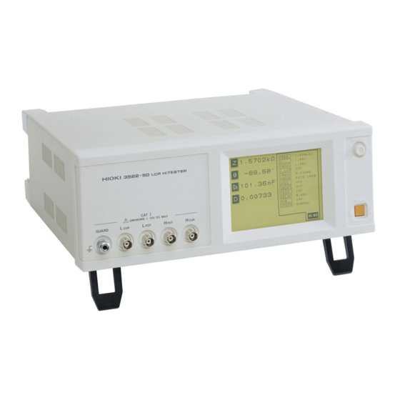
Summary of Contents for Hioki 3522-50
- Page 1 Instruction Manual For...は専用機種。複数の場合は「/」で区切る。不要の場合はとる。 形名を入力。 複数の場合は「/」で区切る。 3522-50 品名を入力。 LCR HiTESTER June 2011 Revised edition 7 3522C981-07 11-06H...
-
Page 3: Table Of Contents
Contents Introduction Shipping Check Safety Points for Attention During Use anual Layout of This M Chapter 1 Overview 1.1 Product Overview 1.2 Product Features 1.3 Names and Functions of Parts Chapter 2 Before Starting Measurement 2.1 Connecting the Power Cord 2.2 Connecting the Test Leads 2.2.1 Establishing the Connections 2.3 Turning the Power On and Off... - Page 4 4.3 Setting the Test Frequency 4.3.1 Control Screen Sequence 4.3.2 Selecting the Input Method 4.3.3 Input Using the Ten Key Screen 4.3.4 Input Using the Digit Screen 4.4 Setting the Test Signal Level 4.4.1 Control Screen Sequence 4.4.2 Selecting the Level Type 4.4.3 Setting the Open Circuit Voltage (V) Level 4.4.4 Setting the Constant Voltage (CV) Level 4.4.5 Setting the Constant Current (CC) Level...
- Page 5 4.11 Setting the Trigger Delay 4.11.1 Control Screen Sequence 4.11.2 Details of the Setting Process 4.12 Setting Averaging 4.12.1 Control Screen Sequence 4.12.2 Details of the Setting Process 4.13 Setting the Testing Speed 4.13.1 Control Screen Sequence 4.13.2 Details of the Setting Process 4.14 Setting and Activating the Comparator 4.14.1 Control Screen Sequence 4.14.2 Setting the Comparator...
- Page 6 4.21 Continuous Test Function 4.21.1 Control Screen Sequence 4.21.2 Details of the Setting Process 4.22 External DC Bias Setting 4.22.1 Control Screen Sequence 4.22.2 Details of the Setting Process 4.23 Setting the Number of Displayed Digits 4.23.1 Control Screen Sequence 4.23.2 Details of the Setting Process 4.24 Setting for Display 4.24.1 Control Screen Sequence...
- Page 7 5.9.4 Returning from Comparator Operation to Normal Testing 5.9.5 Screen Copy Mode 5.9.6 Auto Print Mode 5.9.7 Manual Print Mode Chapter 6 Maintenance, Adjustment, and Disposal 6.1 Maintenance and Servicing 6.2 How to Change the Power Supply Fuse and Change the Power Supply Voltage 6.3 Shipping the Unit 6.4 Troubleshooting Checklist...
- Page 9 ──────────────────────────────────────────────────── Introduction Thank you for purchasing the HIOKI "3522-50 LCR HiTESTER." To obtain maximum performance from the product, please read this manual first, and keep it handy for future reference. This manual contains information and points for attention which are necessary for safe operation of the unit and for storing it safely in proper operational condition.
-
Page 10: Shipping Check
In particular, check the accessories, panel switches, and connectors. If damage is evident, or if it fails to operate according to the specifications, contact your dealer or Hioki representative. Check the 3522-50 unit and the supplied accessories... -
Page 11: Safety
──────────────────────────────────────────────────── Safety This manual contains information and warnings essential for safe operation of the product and for maintaining it in safe operating condition. Before using the product, be sure to carefully read the following safety notes. This product is designed to comply with IEC 61010 Safety Standards, WARNING and has been thoroughly tested for safety prior to shipment. - Page 12 ──────────────────────────────────────────────────── Measurement categories (Overvoltage categories) This instrument complies with CAT I safety requirements. To ensure safe operation of measurement instruments, IEC 61010 establishes safety standards for various electrical environments, categorized as CAT I to CAT IV, and called measurement categories. CAT I Secondary electrical circuits connected to an AC electrical outlet through a transformer or similar device.
-
Page 13: Points For Attention During Use
The 3522-50 contains certain interior components which are at very high voltages. Never remove the cover of the unit, because to do so is very dangerous. Various connectors are present on the outside of the 3522-50. Never CAUTION connect any cable to any of these connectors without first turning off the power supply and removing the power cord. -
Page 14: Layout Of This Manual
──────────────────────────────────────────────────── Layout of This Manual Chapter 1 Overview Describes the product generally, and lists the parts and functions. Chapter 2 Before Starting Measurement How to connect the power cord etc., and important precautions before operation. Chapter 3 Outline of Operation Explains the touch panel and basic testing. -
Page 15: Chapter 1 Overview
Overview 1.1 Product Overview The HIOKI 3522-50 LCR HiTESTER is an impedance meter which uses a touch panel as the user interface. This interactive touch panel enables extremely easy operation. The test frequency can be set DC and from 1 mHz to 100 kHz at high resolution. -
Page 16: Product Features
──────────────────────────────────────────────────── 1.2 Product Features Wide range of test frequencies The test frequency can be selected from a wide range - DC, 1 mHz to 100 kHz - at high resolution. Frequency dependent assessment of electronic components and materials, etc., is possible. Constant voltage and constant current testing Assessment of dependence upon voltage or current is possible. -
Page 17: Names And Functions Of Parts
──────────────────────────────────────────────────── 1.3 Names and Functions of Parts Liquid crystal display Contrast adjustment knob Test terminals Power switch Front View Liquid crystal display This is a 5-inch liquid crystal display fitted with a touch panel. It also serves to provide input keys. Power switch Turns the power for the unit on and off. - Page 18 ──────────────────────────────────────────────────── Power input socket Optional equipment interface with voltage selector EXT I/O connector Key lock switch Rear View Power input socket (internally fused type) with voltage selector Connect the supplied power cord here. Optional equipment interface Optional interface boards are connected here. EXT I/O connector For input of an external trigger signal and output of comparator results.
- Page 19 ──────────────────────────────────────────────────── Handle Stand Left View Stand Can be opened to tilt the unit upwards. Do not apply strong downward pressure with the stand extended. CAUTION Damage to the stand will result. Handle Used when carrying the unit. ──────────────────────────────────────────────────── 1.3 Names and Functions of Parts...
- Page 20 ──────────────────────────────────────────────────── ──────────────────────────────────────────────────── 1.3 Names and Functions of Parts...
-
Page 21: Chapter 2 Before Starting Measurement
Before Starti g Measurement 2.1 Connecting the Power Cord When a 3522-50 unit is ordered, the supply voltage is set in the WARNING factory to the value specified, which can be 100 V, 120 V, 220 V, or 240 V. The maximum rated power (with all options fitted) is 40 VA. -
Page 22: Connecting The Test Leads
The maximum voltage which can be applied to the test terminals of the CAUTION 3522-50 unit is 10 V DC. If a DC voltage greater than this is applied continuously, the unit may be damaged. (For how to apply a DC bias voltage, refer to Section 5.7, "Supplying DC Bias") - Page 23 NOTE figure. Test fixture No test cables are included with the 3522-50 unit. They must be purchased separately. (For details, refer to Section 7.4, "Options") If all four terminals are left floating, the numbers which appear on the display are completely meaningless.
-
Page 24: Turning The Power On And Off
──────────────────────────────────────────────────── 2.3 Turning the Power On and Off How to turn the power on 1. Turn on the power switch on the front panel. The Initial screen will be displayed on the liquid crystal display. Off On The test conditions will start off the same as they were when last the power was turned off. -
Page 25: Chapter 3 Outline Of Operation
CAUTION objects that could damage the touch screen. The 3522-50 uses a touch panel for setting and changing all of the test conditions. Simply by touching the LCD screen at certain areas - termed soft keys - which appear in reverse video, the items associated with these soft keys, and numerical values, can be selected. -
Page 26: About The Screen
──────────────────────────────────────────────────── 3.2 About the Screen (1) The Initial screen When the power is first turned on, the basic screen for controlling the 3522- 50 immediately appears, called the "Initial screen". A maximum of four of the test parameters (L, C, R, etc.) can be set for display, and all of the test conditions can be checked, on this Initial screen. - Page 27 ──────────────────────────────────────────────────── (3) The Parameter setting screen Pressing a parameter key on the Initial screen causes the Parameter setting screen to be displayed, using which the test parameters to be displayed (up to a maximum of four) are selected. By pressing a key for any test parameter, that parameter is set to be displayed, and the unit automatically returns to displaying the Initial screen again.
-
Page 28: Control Screen Sequence
──────────────────────────────────────────────────── 3.2.1 Control Screen Sequence The basic flow for the change of screens as control operation is performed is as follows. The measurement values can be checked in real time on all of the screens. The measured values of any of the test parameters can be displayed for checking (up to a maximum of four) and all of the test conditions can be checked on the Initial screen. -
Page 29: Basic Measurement
──────────────────────────────────────────────────── 3.3 Basic Measurement In order to explain the basic operation of the 3522-50 unit, as an example, the procedure will be shown for establishing the following settings: Example Sample to be tested 85 μF Capacitor Test conditions Test frequency... -
Page 30: Setting The Test Parameters To Be Displayed (Cs, D)
──────────────────────────────────────────────────── 3.3.2 Setting the Test Parameters to be Displayed (Cs, D) Here the first (i.e., the uppermost) parameter key will be set to capacitance Cs, and the third parameter key will be set to loss coefficient D. After Setting Before Setting Setting procedure 1. - Page 31 ──────────────────────────────────────────────────── 3. In order to change the third parameter displayed on the Initial screen, press the third parameter key. Initial Screen 4. The Parameter setting screen is displayed. Press on this screen, and the display will automatically return to displaying the Initial screen, with the loss coefficient D being displayed as the third parameter.
-
Page 32: Setting The Test Frequency
──────────────────────────────────────────────────── 3.3.3 Setting the Test Frequency The following explanation shows how to set the test frequency to 120 Hz, as an example. Before Setting After Setting Setting procedure 1. On the Initial screen, press the key, and the Menu screen will be displayed. Initial Screen 2. - Page 33 ──────────────────────────────────────────────────── There are actually two frequency setting screens. The display can be switched over between these two screens just by pressing a particular soft key. The test frequency is input using the The Digit screen igit keys. The Ten key screen A numerical value for the test frequency is input directly.
- Page 34 ──────────────────────────────────────────────────── 3. Press the keys , and succession on the ten key pad. If you make a mistake, press the key to clear the value entered so far, and start again. Then press the key, and check that the test frequency value input is indeed 120 Hz. NOTE The numerical value input for the test frequency cannot be checked until one of the...
-
Page 35: Setting The Constant Voltage Level
──────────────────────────────────────────────────── 3.3.4 Setting the Constant Voltage Level The following explanation shows, as an example, how to set the value for the constant voltage level to 0.4 V. Before Setting After Setting Setting procedure 1. On the Initial screen, press the key, and the Menu screen will be displayed. - Page 36 ──────────────────────────────────────────────────── 3. Because you for example want to set the value for the constant voltage (CV), press the key. Then check that the key changes to black figures on a white ground (i.e., in non- reversed video), which confirms that constant voltage has been properly selected.
-
Page 37: Setting Open Circuit Compensation
──────────────────────────────────────────────────── 3.3.5 Setting Open Circuit Compensation The following explanation shows, as an example, how to set up ALL open circuit compensation, with which open circuit compensation values for all of the test frequencies are determined and adjusted. Before Setting After Setting Setting procedure 1. - Page 38 ──────────────────────────────────────────────────── 4. Press the key so as to select ALL compensation, with which open circuit compensation values for all the test frequencies will be determined and adjusted. Open Circuit Compensation Screen 5. A Confirmation screen will be displayed for confirmation of ALL open circuit compensation. If it is OK to proceed, press the key.
- Page 39 ──────────────────────────────────────────────────── 7. If the compensation process has terminated satisfactorily, a Confirmation screen as shown to the left is displayed. The residual component at the frequency of 100 kHz with the test cables separated (open circuited), and its phase angle, are shown on the screen.
-
Page 40: Setting Short Circuit Compensation
──────────────────────────────────────────────────── 3.3.6 Setting Short Circuit Compensation The following explanation shows, as an example, how to set up ALL short circuit compensation, with which short circuit compensation values for all of the test frequencies are determined and adjusted. After Setting Before Setting Setting procedure 1. - Page 41 ──────────────────────────────────────────────────── 4. Press the key so as for example to select ALL compensation, with which short circuit compensation values for all the test frequencies will be determined and adjusted. Short Circuit Compensation Screen 5. A Confirmation screen will be displayed for confirmation of ALL short circuit compensation.
-
Page 42: Starting Testing
──────────────────────────────────────────────────── 7. If the compensation process has terminated satisfactorily, a Confirmation screen as shown to the left is displayed. The residual component at the frequency of 100 kHz with the test cables connected together (short circuited), and its phase angle, are shown on the screen. -
Page 43: Chapter 4 Detailed Description Of Functions
──────────────────────────────────────────────────── Chapter 4 Detailed Description of Functions 4.1 Description of the Screens The Initial screen, Menu screen, Application menu screen will be explained. ──────────────────────────────────────────────────── 4.1 Description of the Screens... -
Page 44: The Initial Screen
13. AVE Number of times for averaging 14. SPEED Testing speed Even if the 3522-50 unit is being used outside the limits of its specification, NOTE test values are sometimes displayed. In this case, the following type of indication appears on the display. -
Page 45: The Menu Screen And Application Menu Screen
──────────────────────────────────────────────────── 4.1.2 The Menu Screen and Application Menu Screen To display the Menu screen Press this key on the Initial screen. It is possible to access various setting screens for changing the various test Initial screen conditions from this screen. To display the Application screen Press the key on the Menu screen. -
Page 46: Setting The Parameters To Be Displayed
──────────────────────────────────────────────────── 4.2 Setting the Parameters to be Displayed From among the total of 14 different test parameters a maximum of four can be selected for their values to be simultaneously displayed on the screen, arranged in any desired order. 4.2.1 Control Screen Sequence Press the parameter key for which you wish to make the Initial screen change. - Page 47 ──────────────────────────────────────────────────── 3. The parameter which you wish to display in the chosen position can be chosen from the following list by pressing the corresponding key. The screen will then automatically revert to the Initial screen, with the desired new parameter being displayed in the appropriate position. impedance (Ω) admittance (S) θ...
-
Page 48: Series Equivalent Circuit Mode And Parallel Equivalent Circuit Mode
4.2.3 Series Equivalent Circuit Mode and Parallel Equivalent Circuit Mode The 3522-50 unit obtains the impedance Z and the phase angle θ by measuring the current and voltage across the test sample. The other measurement parameters, like an inductive component L, a capacitive component C, a resistive component R, etc. -
Page 49: Setting The Test Frequency
──────────────────────────────────────────────────── 4.3 Setting the Test Frequency Sometimes the value for the test frequency should be changed according to the type of sample being tested. There are two types of method for inputting the frequency for testing. Either of two different screens can be selected, according to which of these two input methods is to be used. -
Page 50: Selecting The Input Method
──────────────────────────────────────────────────── 4.3.2 Selecting the Input Method 1. On the Initial screen, press the key, and the Menu screen will be displayed. 2. Press the key on the Menu screen, and the display will change over to the one of the Frequency setting screens which was previously used. 3. -
Page 51: Input Using The Ten Key Screen
──────────────────────────────────────────────────── 4.3.3 Input Using the Ten Key Screen 1. Access to the following Ten key screen. Numeric keypad Shows the currently set test frequency Shows the test frequency input so far Returns to the Initial screen Units keys (shown in non-reversed video, until the numerical value for the frequency has been input) 2. -
Page 52: Input Using The Digit Screen
──────────────────────────────────────────────────── 4.3.4 Input Using the Digit Screen 1. Access to the following Digit screen. Monitor display portion ・Test frequency ・Test signal level ・Voltage between test samples ・Limit value ・Current flowing through the test sample Changes the test frequency to DC. Shows the current test frequency Multiplies the test... -
Page 53: Setting The Test Signal Level
The value of the test signal level may change according to the sample which is being tested. With the 3522-50, it is possible to vary the level of the test signal applied to the object under test over a wide range using the following three methods: The value of the open circuit voltage is set. -
Page 54: Selecting The Level Type
──────────────────────────────────────────────────── 4.4.2 Selecting the Level Type Be absolutely sure not to change over between constant current (CC) level CAUTION and constant voltage (CV) level with the test terminals still connected to the sample to be tested. Doing so may damage the test sample. 1. - Page 55 ──────────────────────────────────────────────────── Even if the 3522-50 unit is being used outside the limits of its specification, NOTE test values are sometimes displayed. In this case, the following type of indication appears on the display, indicating a value which is not guaranteed.
-
Page 56: Setting The Open Circuit Voltage (V) Level
──────────────────────────────────────────────────── 4.4.3 Setting the Open Circuit Voltage (V) Level 1. Press this key to set open circuit voltage (V), and the monitor display will Test signal level change immediately. setting screen Monitor display portion Test frequency Open circuit voltage Voltage between test samples Limit value for the current... -
Page 57: Setting The Constant Voltage (Cv) Level
──────────────────────────────────────────────────── 4.4.4 Setting the Constant Voltage (CV) Level 1. Press this key to set constant voltage (CV), and the monitor display will Test signal level change immediately. setting screen Monitor display Test frequency Set value for constant voltage Voltage between test samples Limit value for the current... -
Page 58: Setting The Constant Current (Cc) Level
──────────────────────────────────────────────────── 4.4.5 Setting the Constant Current (CC) Level 1. Press this key to set constant current (CC), and the monitor display will Test signal level change immediately. setting screen Monitor display ・Test frequency ・Set value for constant current ・Current flowing through the test sample ・Limit value for the... -
Page 59: Setting The Voltage/Current Limit
3522-50 unit will limit the voltage, or current, so as keep it below this specified limit value. -
Page 60: Details Of The Setting Process
──────────────────────────────────────────────────── 4.5.2 Details of the Setting Process 1. Press the key on the Initial screen to display the Menu screen. Initial screen 2. Press the key on the Menu screen to display the one of the Limit setting screens. Menu screen When the test signal level type When the test signal level type is voltage (V or CV) - Page 61 ──────────────────────────────────────────────────── 4. The limit function can be turned on and off by pressing the appropriate one of the following keys (The key which has been pressed changes to non- reversed video). : The limit function is turned on. : The limit function is turned off. Whether the limit function is on or off can be checked from the change on the monitor display.
-
Page 62: Setting The Ranging
──────────────────────────────────────────────────── 4.6 Setting the Ranging Using AUTO, the 3522-50 unit can automatically select the most appropriate test range. This is useful when testing a sample whose impedance varies greatly with frequency, or whose nature is unknown. The test range can also be fixed using HOLD, which provides the quickest testing. -
Page 63: Setting The Ranging
The test range is fixed, and may only be altered manually. HOLD : 4.6.3 Setting AUTO Ranging 1. Press this key, and the 3522-50 will automatically be set to the most suitable Ranging setting test range. At this time, the AUTO key and the key corresponding to the screen current test range will be shown in non-reverse video. -
Page 64: Setting The Ranging To Hold
──────────────────────────────────────────────────── 4.6.4 Setting the Ranging to HOLD 1. There are two ways of setting the ranging to HOLD: Ranging setting screen 1) While AUTO ranging is set, press the key, and then this key will go into non-reverse video, and the currently most suitable range will be held fixed. - Page 65 Section 4.9, "Open Circuit Compensation and Short Circuit Compensation". Even if the 3522-50 unit is being used outside the limits of its specification, test values are sometimes displayed. In this case, the following type of indication "reference value" appears on the display, indicating a value which is not guaranteed.
-
Page 66: Open Circuit Compensation
Compensation is performed at all the test frequencies. SPOT compensation Compensation is performed for one specified test frequency only. The testing accuracy specified in the specification of the 3522-50 unit assumes NOTE that open circuit compensation and short circuit compensation is being performed, as appropriate. -
Page 67: Setting The Compensation Method
──────────────────────────────────────────────────── 4.7.2 Setting the Compensation Method 1. Arrange the test leads as closely as possible to their configuration in which measurement will be performed, and make sure that the HIGH and LOW leads are not contacted together. 2. When the open circuit compensation is performed, execute the guarding process. -
Page 68: All Compensation
──────────────────────────────────────────────────── 4.7.3 ALL Compensation 1. To select ALL compensation, press this key with the Open circuit Open circuit compensation screen displayed. compensation screen Open Circuit Compensation Screen 2. A Confirmation screen will appear for confirmation. If it is OK to proceed, press the key;... - Page 69 ──────────────────────────────────────────────────── 3. When the key is pressed, the ALL open circuit compensation process starts. After about 2 minutes, the determination and adjustment of the open circuit compensation values is complete. Interrupting the ALL compensation process: To interrupt the ALL compensation process, press the key on this screen.
-
Page 70: Spot Compensation
──────────────────────────────────────────────────── 4.7.4 Spot Compensation 1. To select SPOT compensation, press this key with the Open circuit Open circuit compensation screen displayed. compensation screen Open Circuit Compensation Screen 2. A numeric keypad is displayed for input of the frequency. Until one of these keys is pressed for input of a numerical value, the previous frequency for which SPOT compensation was performed is displayed. - Page 71 ──────────────────────────────────────────────────── SPOT compensation for the same frequency as previously Just press the key. SPOT compensation will be started using the same frequency which was used for the last episode of SPOT compensation. SPOT compensation for some new frequency Input the frequency for compensation using the numeric keypad. Frequency range which can be set : 1 mHz to 100.0 kHz If you attempt to set a test frequency greater than 100 kHz, it will NOTE...
- Page 72 ──────────────────────────────────────────────────── 4. When you press the key, the SPOT open circuit compensation process starts. Interrupting the SPOT compensation process: To interrupt the SPOT compensation process, press the key on this screen. The compensation process will stop and the display will revert to the Initial screen.
-
Page 73: When An Error Message Appears And Compensation Has Stopped
──────────────────────────────────────────────────── 4.7.5 When an Error Message Appears and Compensation Has Stopped When an error message appears and compensation has stopped, open circuit compensation is turned OFF. The open circuit compensation process is quite sensitive to noise - both noise originating externally and induced noise. Therefore, if open circuit compensation has been interrupted with a fault, you should check the following points before starting the compensation process again: Check that the test cables are properly connected. -
Page 74: Short Circuit Compensation
Compensation is performed at all the test frequencies. SPOT compensation Compensation is performed for one specified test frequency only. The testing accuracy specified in the specification of the 3522-50 unit assumes NOTE that open circuit compensation and short circuit compensation is being performed, as appropriate. -
Page 75: Setting The Compensation Method
──────────────────────────────────────────────────── 4.8.2 Setting the Compensation Method 1. A shorting bar is used. This shorting bar is for short circuiting together the ends of the test leads. Use an object whose impedance is as low as possible. Possible Not possible Metallic wire Metallic plate If you use a metallic wire or the like as a shorting bar, try to ensure that it is NOTE... - Page 76 ──────────────────────────────────────────────────── 3. On the Initial screen, press the key, and the Menu screen will be displayed. 4. Press the key on the Menu screen, and the Short circuit compensation screen will be displayed. ALL key SPOT key OFF key Press this key to interrupt setting and return to the Initial screen.
-
Page 77: All Compensation
──────────────────────────────────────────────────── 4.8.3 ALL Compensation 1. To select ALL compensation, press this key with the Short circuit Short circuit compensation screen displayed. compensation screen Short Circuit Compensation Screen 2. A Confirmation screen will appear for confirmation. To proceed, press the key; if not, press the key to return to the Short circuit compensation screen. - Page 78 ──────────────────────────────────────────────────── 3. When you press the key, the ALL short circuit compensation process starts. After about 2 minutes, the determination and adjustment of the short circuit compensation values is complete. Interrupting the ALL compensation process: To interrupt the ALL compensation process, press the key on this screen.
-
Page 79: Spot Compensation
──────────────────────────────────────────────────── 4.8.4 Spot Compensation 1. To select SPOT compensation, press this key with the Short circuit Short circuit compensation screen displayed. compensation screen Short Circuit Compensation Screen 2. A numeric keypad is displayed for input of the frequency. Until one of these keys is pressed for input of a numerical value, the previous frequency for which SPOT compensation was performed is displayed. - Page 80 ──────────────────────────────────────────────────── When compensation is to be performed for some new frequency: Input the frequency for compensation using the numeric keypad. Frequency range which can be set : 0.000 Hz (DC) to 100 kHz If you attempt to set a test frequency greater than 100 kHz, it will NOTE automatically be reduced to 100 kHz.
- Page 81 ──────────────────────────────────────────────────── 4. When you press the key, the SPOT short circuit compensation process starts. Interrupting the SPOT compensation process: To interrupt the SPOT compensation process, press the key on this screen. The compensation process will stop and the display will revert to the Initial screen.
-
Page 82: When An Error Message Appears And Compensation Has Stopped
──────────────────────────────────────────────────── 4.8.5 When an Error Message Appears and Compensation Has Stopped When an error message appears and compensation has stopped, short circuit compensation is turned off. Check the following points before starting the short circuit compensation process again: Check that the test cables are properly connected. Check that the test cables are properly shorted together with the shorting bar. -
Page 83: Open Circuit Compensation And Short Circuit Compensation
──────────────────────────────────────────────────── 4.9 Open Circuit Compensation and Short Circuit Compensation The residual impedance component of the test fixture can be considered in terms of an equivalent circuit as shown in the figure. Further, because the measured value Zm for impedance includes this residual component, therefore, in order to obtain the genuine impedance value, it is necessary to compensate the measured value in terms of the open circuit impedance residual component and the short circuit residual component, which... - Page 84 ──────────────────────────────────────────────────── The determination of test range is performed according to the measured NOTE value Zm for impedance. Therefore it may happen that testing cannot be performed, when HOLD is on, if the test range is determined merely according to the value of impedance of the sample under test. In this case, you should set the test range in consideration both of the impedance of the test sample and also of the residual impedance components of the test fixture.
-
Page 85: Setting The Trigger
──────────────────────────────────────────────────── 4.10 Setting the Trigger The trigger can either be set to internal trigger, when continuous testing is performed while automatically generating an internal trigger signal, or external trigger, when a trigger signal is input from the outside either manually or automatically. 4.10.1 Control Screen Sequence Initial screen Press the... -
Page 86: Details Of The Setting Process
──────────────────────────────────────────────────── 4.10.2 Details of the Setting Process 1. Press the key on the Initial screen to display the Menu screen. Initial screen 2. Press the key on the Menu screen to display the Trigger setting screen. Menu screen The currently set trigger is displayed here. Press to select external trigger. - Page 87 When inputting the trigger signal through the EXT I/O connector: Testing is performed once, each time a negative sense pulse signal is supplied to the EXT I/O connector on the rear panel of the 3522-50. (For details, refer to Section 5.5, "The EXT I/O Connector") When inputting the trigger signal through the interface: Testing is performed once, when the "...
-
Page 88: Setting The Trigger Delay
──────────────────────────────────────────────────── 4.11 Setting the Trigger Delay The delay time period from input of the trigger signal to reading of the test data can be set. The value of the trigger delay period can be set from 10 ms to 9.99 s, with a resolution of 10 ms. With this function it is possible to ensure that testing is started after the connection condition of the object being tested and the test cables has stabilized. -
Page 89: Details Of The Setting Process
──────────────────────────────────────────────────── 4.11.2 Details of the Setting Process 1. Press the key on the Initial screen. The Menu screen will be displayed. Initial screen 2. Press the key on the Menu screen. The Trigger delay setting screen will be displayed. Menu screen Press this key when setting is completed to return to the Initial screen. - Page 90 ──────────────────────────────────────────────────── Canceling the trigger delay function Press the key to set the trigger delay period to 0.00 s. This will cancel the trigger delay function. ──────────────────────────────────────────────────── 4.11 Setting the Trigger Delay...
-
Page 91: Setting Averaging
──────────────────────────────────────────────────── 4.12 Setting Averaging With the averaging function, the measured values can be averaged. Using this function, it is possible to reduce fluctuations in the measured value display. The averaging can be performed over 2, 4, 8, 16, 32, or 64 times that measurement is performed. -
Page 92: Details Of The Setting Process
──────────────────────────────────────────────────── 4.12.2 Details of the Setting Process 1. Press the key on the Initial screen to display the Menu screen. Initial screen 2. Press the key on the Menu screen to display the Averaging setting screen. Menu screen The selected number is displayed, and averaging is set. When the setting is completed, press this key to return to the Initial screen. - Page 93 ──────────────────────────────────────────────────── 4. When the setting has been established as above, press the key to return to the Initial screen. Stopping the averaging function On the Averaging setting screen, press the key. This key will go into non-reversed video, and the averaging function will be terminated. OFF key ────────────────────────────────────────────────────...
-
Page 94: Setting The Testing Speed
──────────────────────────────────────────────────── 4.13 Setting the Testing Speed The testing speed can be set. The slower the testing speed is, the more accurate are the results. The testing speed can be set to one of three values: low accuracy testing is performed at high speed FAST the speed used for normal testing NORM... -
Page 95: Details Of The Setting Process
──────────────────────────────────────────────────── 4.13.2 Details of the Setting Process 1. Press the key on the Initial screen to display the Menu screen. Initial screen 2. Press the key on the Menu screen to display the Test speed setting screen. Menu screen The test speed currently set is displayed. FAST key NORM key SLOW key... -
Page 96: Setting And Activating The Comparator
LO (less than the lower limit value). Moreover, a corresponding signal can be output via the EXT I/O connector on the rear panel of the 3522-50 unit. The following setting methods are available on the comparator: Absolute value setting method (ABS) The upper limit value and the lower limit value are set as absolute numerical values. -
Page 97: Control Screen Sequence
──────────────────────────────────────────────────── 4.14.1 Control Screen Sequence Initial screen Press the key. Menu screen Press the key. Application menu screen Press the key. Activate the comparator. To change the comparator settings, Comparator screen press the key. Choose the comparator setting method Decision conditions setting screen (ABS, %, or Δ%) Input the decision conditions. - Page 98 ──────────────────────────────────────────────────── Initial Screen Comparator Screen On the Scaling screen, the Comparator scaling screen can be also accessed NOTE by same key operations. The comparator is activated for the scaling measured value. For the scaling function, refer to Section 4.15. Scaling Screen Comparator Scaling Screen ────────────────────────────────────────────────────...
- Page 99 ──────────────────────────────────────────────────── 4. Set the first and third parameters to be the two parameters which you wish to measure. (Refer to the section on display parameter setting for details upon how to make the setting.) Shows the results of the decisions made by the comparator.
-
Page 100: Returning From Comparator Operation To Normal Testing
──────────────────────────────────────────────────── 4.14.3 Returning from Comparator Operation to Normal Testing 1. Press the key on the Comparator screen or the Comparator scaling screen to display the Menu screen. Initial screen 2. Press the key on the Menu screen to display the Application menu screen. - Page 101 ──────────────────────────────────────────────────── Percentage (%) Setting Screen Absolute Value (ABS) Setting Screen Deviation Percentage (Δ%) Setting Screen ──────────────────────────────────────────────────── 4.14 Setting and Activating the Comparator...
-
Page 102: Setting The Upper Or Lower Limit Value As An Absolute Value (Abs)
──────────────────────────────────────────────────── 4.14.5 Setting the Upper or Lower Limit Value as an Absolute Value (ABS) 1. Press this key on the Conditions setting screen displayed to select the Condition setting absolute value setting mode. screen At this time the key will go into non-reversed video, and simultaneously keys will appear for setting the upper and lower limit values. - Page 103 ──────────────────────────────────────────────────── 3. Select the units using one of the units keys: step the units up step the units down p -- n -- μ -- m -- (none) -- k -- M <= Units down Units up => Pressing the key causes the upper limit value to be set and the screen display to return to the Conditions setting screen.
-
Page 104: Setting The Upper Or Lower Limit Value As A Percentage (%) Relative To A Standard Value
──────────────────────────────────────────────────── 4.14.6 Setting the Upper or Lower Limit Value as a Percentage (%) Relative to a Standard Value 1. Press this key on the Conditions setting screen to select the percentage value Condition setting setting mode. screen At this time the key will go into non-reversed video, and simultaneously a key will appear for inputting the reference value,... - Page 105 ──────────────────────────────────────────────────── 3. Select the units using one of the units keys: step the units up step the units down p -- n -- μ -- m -- (none) -- k -- M <= Units down Units up => Pressing the key causes the upper limit value to be set and the screen display to return to the Conditions setting screen.
- Page 106 ──────────────────────────────────────────────────── 5. The lower limit value is set in a manner identical to the upper limit value, mutatis mutandis. The setting can be made in the range : -999.99% to +999.99% The actual internal operation consists of calculating the lower-limit value of NOTE comparison using the equation given below, and comparing it to the measurement value to enable a decision to be made.
-
Page 107: Displaying Measurement Values As Deviations From The Reference Value (Δ%)
──────────────────────────────────────────────────── 4.14.7 Displaying Measurement Values as Deviations from the Reference Value (Δ%) 1. Press this key on the Conditions setting screen to select the deviation Condition setting percentage mode. screen At this time the key will go into non-reversed video, and simultaneously a key will appear for inputting the reference value, keys will appear for the upper and lower limit... - Page 108 ──────────────────────────────────────────────────── The comparator decisions are made in the following order: NOTE 1) If the measured value is "OVER FLOW", HI is displayed, and the value is "UNDER FLOW", LO is displayed. 2) Is the measured value greater than the lower limit value or not? If not (NG decision result), then LO is displayed.
-
Page 109: Setting And Activating The Scaling
──────────────────────────────────────────────────── 4.15 Setting and Activating the Scaling Scaling applies a correction function to the measurement value. This function can be used to provide compatibility among measurement devices. Set the compensation coefficient a and b for the measurement values of the first and third parameters to compensate by the following expression. -
Page 110: Setting Scaling
──────────────────────────────────────────────────── 4.15.2 Setting Scaling 1. Press the key on the Initial screen to display the Menu screen. Initial screen 2. Press the key on the Menu screen to display the Application menu screen. Menu screen 3. Press the key on the Application menu screen to display the Scaling screen. -
Page 111: Canceling The Scaling Function
──────────────────────────────────────────────────── 4. Set the first and third parameters to be the two parameters which you wish to measure. (Refer to the section on display parameter setting for details upon how to make the setting.) Shows the first compensation coefficient setting. Shows the third compensation coefficient setting. -
Page 112: Setting The Compensation Coefficient (A, B)
──────────────────────────────────────────────────── 4.15.4 Setting the Compensation Coefficient (a, b) 1. Access the Scaling screen. 2. On the Scaling screen, press the key which you wish to change. The Conditions setting screen will be displayed. 3. Press the key, and a screen will appear for setting the compensation coefficient a. - Page 113 ──────────────────────────────────────────────────── 4. Set the compensation coefficient b as the same way. The setting can be made in the range : -200.00M to +200.00M step the units up step the units down p -- n -- μ -- m -- (none) -- k -- M <= Units down Units up =>...
-
Page 114: Panel Save Function
──────────────────────────────────────────────────── 4.16 Panel Save Function All of the test conditions can be saved as a "panel", up to a maximum of 30 such stored panels (i.e., sets of stored test conditions). The test conditions which are saved are: Display parameters Test range Set value for averaging Test frequency... -
Page 115: Details Of The Setting Process
──────────────────────────────────────────────────── 4.16.2 Details of the Setting Process 1. Press the key on the Initial screen to display the Menu screen. Initial screen 2. Press the key on the Menu screen to display the Application menu screen. Menu screen 3. Press the key on the Application menu screen to display the Panel number selection screen. - Page 116 ──────────────────────────────────────────────────── 4. When you have decided upon the panel number under which the present test conditions will be saved, press the corresponding panel number key to select Saving name Test conditions to be saved save the current test conditions with the saving name, and the display automatically reverts to the Initial screen.
- Page 117 Under normal conditions of use, the average life of the backup battery is about 10 years. If the internal battery becomes exhausted, it is no longer possible to save the test conditions. You should have the battery changed by an approved HIOKI service facility (which is chargeable). ────────────────────────────────────────────────────...
-
Page 118: Panel Load Function
──────────────────────────────────────────────────── 4.17 Panel Load Function Using the panel load function, saved test conditions can be loaded. The test conditions which are saved: Display parameters Test range Set value for averaging Test frequency Open and short circuit compensation values Set value for test speed Test signal level Setting for trigger value Beep sound setting... -
Page 119: Details Of The Setting Process
──────────────────────────────────────────────────── 4.17.2 Details of the Setting Process 1. Press the key on the Initial screen to display the Menu screen. Initial screen 2. Press the key on the Menu screen to display the Application menu screen. Menu screen 3. Press the key on the Application menu screen to display the Panel load screen. - Page 120 Under normal conditions of use, the average life of the backup battery is about 10 years. If the internal battery becomes exhausted, it is no longer possible to save the test conditions. You should have the battery changed by an approved HIOKI service facility (which is chargeable). ────────────────────────────────────────────────────...
-
Page 121: Setting The Beep Sound
──────────────────────────────────────────────────── 4.18 Setting the Beep Sound The beep sound which is produced each time that a soft key is pressed, and the beep sound which is produced when the comparator makes decisions, can be turned on and off individually. 4.18.1 Control Screen Sequence Initial screen Press the key. -
Page 122: Details Of The Setting Process
──────────────────────────────────────────────────── 4.18.2 Details of the Setting Process 1. Press the key on the Initial screen to display the Menu screen. Initial screen 2. Press the key on the Menu screen to display the Application menu screen. Menu screen 3. Press the key on the Application menu screen to display the Beep sound setting screen. -
Page 123: Enlarged Display Of Measurement Values
──────────────────────────────────────────────────── 4.19 Enlarged Display of Measurement Values The measurement values and comparator decision results can be displayed in enlarged form. This function is convenient when the unit is used under constant measurement conditions. After powering off on the Magnification display screen, the same screen is displayed when the power is turned on again. -
Page 124: Details Of The Setting Process
──────────────────────────────────────────────────── 4.19.2 Details of the Setting Process 1. Press the key on the Initial screen to display the Menu screen. Initial screen 2. Press the key on the Menu screen to display the Application menu screen. Menu screen 3. Press the key on the Application menu screen to display the Magnification display screen. -
Page 125: System Reset
──────────────────────────────────────────────────── 4.20 System Reset All of the settings will revert to the factory original settings. 4.20.1 Control Screen Sequence Initial screen Press the key. Menu screen Press the key. Application menu screen Press the key. Initial screen ──────────────────────────────────────────────────── 4.20 System Reset... -
Page 126: Details Of The Setting Process
──────────────────────────────────────────────────── 4.20.2 Details of the Setting Process 1. Press the key on the Initial screen to display the Menu screen. Initial screen 2. Press the key on the Menu screen to display the Application menu screen. Menu screen 3. Press the key on the Application menu screen to display the System reset screen. - Page 127 ──────────────────────────────────────────────────── The settings established at the factory are as follows: |Z|, θ Test parameters Test frequency 1 kHz Open circuit voltage (V) setting Test signal level 1.000 V Open circuit voltage (V) set value Constant voltage (CV) set value 1.000 V Constant current (CC) set value 10.00 mA Limit function...
-
Page 128: Continuous Test Function
──────────────────────────────────────────────────── 4.21 Continuous Test Function It is possible to read in order test conditions which have been saved using the panel save function, and to perform continuous testing. Up to five panel numbers can be selected in a page for the continuous testing. -
Page 129: Details Of The Setting Process
──────────────────────────────────────────────────── 4.21.2 Details of the Setting Process This section describes procedure when performing continuous testing with panel numbers 6, 8, and 10 for example. 1. Save the continuous testing conditions using the panel save function to the panel numbers 6, 8, and 10. The continuous testing is performed for the first and third parameters which have been saved. - Page 130 ──────────────────────────────────────────────────── 5. Using the keys make a display of panel numbers which are previously saved. Continuous Test Screen The panel numbers which are not saved or which are invalid even if saved NOTE (when the both first and third parameters are off, or when the parameters are other than Rs and Rp during DC measurement) are not displayed.
- Page 131 ──────────────────────────────────────────────────── 7. Press the to start test. The test result is displayed when the tests of each panel numbers are terminated. When the comparator test, individual decision The first result and parameter test AND result result displayed. The third parameter test result If the displaying page is switched to other page after test completed, the NOTE...
-
Page 132: External Dc Bias Setting
──────────────────────────────────────────────────── 4.22 External DC Bias Setting The external DC bias function is available for test of supplying DC bias or batteries and if the test result is "OVER FLOW" or failed. Set this function to ON. For supplying external DC bias, refer to Section 5.7, "Supplying DC Bias". When using the 9268, 9268-01, or 9269 DC-bias units, turn off the DC-bias function. -
Page 133: Details Of The Setting Process
──────────────────────────────────────────────────── 4.22.2 Details of the Setting Process 1. Press the key on the Initial screen to display the Menu screen. Initial screen 2. Press the key on the Menu screen to display the Application menu screen. Menu screen 3. Press the key on the Application menu screen to display the External DC bias setting screen. -
Page 134: Setting The Number Of Displayed Digits
──────────────────────────────────────────────────── 4.23 Setting the Number of Displayed Digits The number of effective digits for measurement can be set on a parameter- by-parameter basis. 4.23.1 Control Screen Sequence Initial screen Press the key. Menu screen Press the key. Application menu screen Press the key. -
Page 135: Details Of The Setting Process
──────────────────────────────────────────────────── 4.23.2 Details of the Setting Process 1. Press the key on the Initial screen to display the Menu screen. Initial screen 2. Press the key on the Menu screen to display the Application menu screen. Menu screen 3. Press the key on the Application menu screen to display the Setting the displayed digits screen. -
Page 136: Setting For Display
──────────────────────────────────────────────────── 4.24 Setting for Display In some applications, such as on a production line or where EXT I/O or interfaces are used, it may not be necessary to display measurement values. This unit allows ON/OFF settings of the display and voltage/current monitors (Vmoni, Imoni) to be made. -
Page 137: Details Of The Setting Process
──────────────────────────────────────────────────── 4.24.2 Details of the Setting Process 1. Press the key on the Initial screen to display the Menu screen. Initial screen 2. Press the key on the Menu screen to display the Application menu screen. Menu screen 3. Press the key on the Application menu screen to display the Display Setting Screen. -
Page 138: Key Lock Function
4.25.1 Turning the Key Lock On and Off This function is activated using the key lock switch on the rear panel of the 3522-50 unit. The key lock function can only be used when the screen is displaying the Initial screen, Comparator screen, Scaling screen, Magnification display screen, or Continuous test screen. -
Page 139: Chapter 5 Applications
──────────────────────────────────────────────────── Chapter 5 Applications 5.1 Example of Comparator Application Making decisions for two items simultaneously (ABS and % settings). First parameter: static capacitance Cp and third parameter: phase angle θ Example will be set as follows: First parameter (ABS setting) Upper limit value 110 nF Lower limit value... - Page 140 ──────────────────────────────────────────────────── Sorting a single item into five bands (% setting). Two decisions can be made relating to the same item, so as to obtain five different combinations of results. Example First parameter and third parameter: impedance , will be set as follows: First parameter Reference value 3.0 kΩ...
-
Page 141: Testing High Impedance Elements
──────────────────────────────────────────────────── 5.2 Testing High Impedance Elements The measured value obtained when testing a high impedance element (such as, for example, a resistor with resistance higher than 100 kΩ) is sometimes unreliable, because such an element is vulnerable to the effects of external interference and the like. -
Page 142: Testing An Element In A Circuit
──────────────────────────────────────────────────── 5.3 Testing an Element in a Circuit Testing an element in a circuit is not possible without guarding. Referring to the following figure, when measuring a resistance value for the resistor R , even if the tips of the two probes are contacted against the ends of the resistor R , considering the sum of the current flowing through the resistor R... -
Page 143: External Interference
──────────────────────────────────────────────────── 5.4 External Interference The 3522-50 is designed to be resistant to errors caused by interference from the test cables or the power supply line. However, if the level of the interference is particularly large, this can cause measurement errors or faulty operation. - Page 144 AC power inlet of the 3522-50 unit, so as to suppress noise from the power supply line. Further benefit can often be obtained by fitting another anti- interference ferrite core on to the power cord at its other end, as close as possible to the plug which connects to the power supply outlet.
-
Page 145: Countermeasures Against Noise From The Test Cables
──────────────────────────────────────────────────── 5.4.2 Countermeasures Against Noise from the Test Cables If interference is producing noise in the test cables, its influence can be moderated by the following countermeasure. Fitting an anti-interference ferrite core on the test cables Pass the test cables through a commercially available anti-interference ferrite core, and fix it close to the test terminals, so as to suppress noise from the test cables. -
Page 146: The Ext I/O Connector
(INDEX), and for input of an external trigger signal, and a signal for performing selection of the number of the panel to be loaded. Connector used DKK: 57RE-40360-730B(D29) Compatible connector DKK : 57-30360 Hirose: RC30-36P or equivalent EXT I/O Connector Pin Numbering (seen from 3522-50) ──────────────────────────────────────────────────── 5.5 The EXT I/O Connector... -
Page 147: Pinouts For The Ext I/O Connector
──────────────────────────────────────────────────── 5.5.1 Pinouts for the EXT I/O Connector Signal line name Input/output Signal line name Input/output number number ――――― ―――― TRIG Input Input ―――― ―――― Input Input ―――― ―――― Input Input ―――――― ――――― PNL0 Input PNL1 Input ―――――― ――――― PNL2 Input M-HI Output... -
Page 148: Signal Lines For The Ext I/O Connector
EXT.COM These are terminals for supplying a power supply voltage from an external device. This enables the 3522-50 unit to be connected to an external device while maintaining the isolation. The range of power voltage which can be connected is from +5 to +24 volts DC. - Page 149 ──────────────────────────────────────────────────── ___________ (8) TRIG When the external trigger is enabled for the 3522-50, measurement is begun when this signal is input. --------------- --------------- (9) PNL0 to PNL2 (Panel page signals) These lines inputs the page which have been saved by the panel save function.
-
Page 150: Circuit Construction And Connections For The Ext I/O Connector
The insulation of the signal lines is for eliminating mutual influences CAUTION between the signals. Any device which is connected to the 3522-50 unit should always be properly protectively grounded. If proper connection to a protective ground is not established, there is a danger of damage to the insulation. -
Page 151: Electrical Characteristics Of The Output Signals
INT GND. The maximum current capacity is 100 mA. Do not connect any external circuit whose current consumption is greater than 100 mA. INT GND is grounded to the chassis of the 3522-50 unit. When using the EXT I/O connector, be sure always to supply power to the external DC power supply. -
Page 152: Testing Using Ext I/O
EXT I/O connector. When a panel number has been selected using the panel load signal at the input of a trigger signal via the EXT I/O connector, the 3522-50 loads the measurement conditions for the panel number and then begins measurement. - Page 153 When the selected panel number falls under either of the following conditions, the NOTE 3522-50 begins measurement without loading the measurement conditions: (1) When more than 2 panel numbers have been selected. (2) The selected panel number is not stored.
-
Page 154: Continuous Testing From Ext I/O
──────────────────────────────────────────────────── 5.6.2 Continuous Testing From EXT I/O It is possible to read in from the EXT I/O connector in order test conditions which have been saved using the panel save function, and to perform as many measurements as desired one after another automatically (continuous testing). - Page 155 ──────────────────────────────────────────────────── (2) Details of the Setting Process This section describes procedure when performing continuous testing with panel numbers 6, 8, and 10 for example. 1. Save the continuous testing conditions on the panel number 6, 8, and 10. The continuous testing is performed for the first and third parameters which have been saved.
- Page 156 ──────────────────────────────────────────────────── 3. When continuous testing is performed using panel numbers 6, 8 and 10, set the following signals via the EXT I/O connector. ────── ───── ────── ──── ──── ──── ──── ──── Signal lines PNL2 PNL1 PNL0 Settings HIGH HIGH HIGH HIGH For details on each signals, panel saving pages, and panel numbers, see Section 5.5.2, "Signal Lines for the EXT I/O Connector."...
- Page 157 ──────────────────────────────────────────────────── An example test timing in this case is shown below. Example When continuous testing is performed using panel numbers 6, 8 and 10: ------------- TRIG (Measurement start signal) Panel no. 6 Panel no. 8 Panel no. 10 conditions set conditions set conditions set ---------------...
- Page 158 ──────────────────────────────────────────────────── 5. When each trigger signal arrives and the panel number is changed, the process follows the timing shown in the next figure. (The figure shows that the panel numbers 6,8 and 10 are tested first and then the panel numbers 2 and 3 are tested.) Conditions set for next measurement (TRIG signal input)
-
Page 159: Supplying Dc Bias
The maximum voltage which can be applied to the test terminals CAUTION of the 3522-50 unit is 10 V DC. If a DC voltage greater than this is applied continuously, the unit may be damaged. Supplying DC bias means that a DC voltage is supplied as a bias to a sample for test whose characteristics are voltage dependent, such as an electrolytic capacitor or a ceramic capacitor. - Page 160 + DC voltage source + − 3522-50 − Sample to be tested GUARD DC Bias Voltage Circuit Use a resistance (R) or inductance (L) which has a large enough impedance with reference to the sample under test (Z).
-
Page 161: How To Supply A Dc Bias Current
DC bias is being supplied to them. Use the 9269 at more 100.1Hz or more with the EXT DC bias of the 3522-50 switched off. Useing the 9268 at less than 100Hz or with the EXT DC bias switched on may result in abnormal measurements or damage to the unit. -
Page 162: The Residual Charge Protection Function
(The maximum voltage for supply to the test terminals of the 3522-50 unit is 10 VDC.) If this is done, there is a danger of damage to the unit. (For how to supply a DC bias voltage, refer to Section 5.7, "Supplying DC Bias".) -
Page 163: 9442 Printer (Option)
Change the settings of the software dip switches (DIP SW) to use the 9442 for the 3522-50. The 9442 is shipped with the function settings for use with the HIOKI 3166 CAUTION CLAMP ON POWER HiTESTER. Before using, always change the settings of the DIP switches. - Page 164 SW 1. Refer to the next table. Switch No. Function ON (ON LINE) OFF (FEED) Software DIP SW1 Input method Parallel Serial Use these settings for the 3522-50 Printing speed High Auto loading Enable Carriage return CR function Carriage return and line feed DIP SW setting...
-
Page 165: Connection Method
──────────────────────────────────────────────────── 6. After setting for the switch number 8 of DIP SW 3 is made, press the ON LINE or FEED switch to complete settings. "Dip SW setting complete!!" is printed out. (3) Setting of the 9593-01 RS-232C INTERFACE Set the communication setting switch on the left of the RS-232C connector to ON. -
Page 166: Control Screen Sequence
──────────────────────────────────────────────────── 5.9.3 Control Screen Sequence Initial screen Press the key. Menu screen Press the key. Application menu screen Press the key. Select the print type. Print mode setting screen SCREEN AUTO MANUAL COPY Output test Output test Output values after values when screen copy test... - Page 167 ──────────────────────────────────────────────────── 5.9.4 Returning from Comparator Operation to Normal Testing 1. Press the key on the Initial screen to display the Menu screen. Initial screen 2. Press the key on the Menu screen to display the Application menu screen. Menu screen 3.
- Page 168 ──────────────────────────────────────────────────── 5.9.5 Screen Copy Mode Prints out the screen copy of the Initial screen. Pressing the key on the Initial screen starts printing. During printing, the key is not displayed, and all keys are invalid. When the printer is not operated for 10 seconds or more after pressing the key, such as case of disconnecting the printer, it stops printing after beep sounds.
- Page 169 ──────────────────────────────────────────────────── 5.9.6 Auto Print Mode The test values are printed out when the test is completed. When the continuous test is performed, the test values are printed out when each test for the panel number is completed. Example of printing Normal test Comparator executing Continuous test...
- Page 170 ──────────────────────────────────────────────────── ──────────────────────────────────────────────────── 5.9 9442 PRINTER (option)
- Page 171 If damage is suspected, check the "Troubleshooting" section before contacting your dealer or Hioki representative. Getting the 3522-50 unit wet or letting oil or dust enter inside its casing will certainly damage it, and is quite likely to cause an electric shock accident or a dangerous conflagration.
- Page 172 ──────────────────────────────────────────────────── Cleaning the unit To clean the product, wipe it gently with a soft cloth moistened with water or mild detergent. Never use solvents such as benzene, alcohol, acetone, ether, ketones, thinners or gasoline, as they can deform and discolor the case.
- Page 173 WARNING supply voltage, in order to avoid the risk of electric shock accident, be quite sure first to turn the main switch of the 3522-50 unit off, and then to remove the power cord. Moreover, after finishing any operation, before reconnecting the...
- Page 174 ──────────────────────────────────────────────────── Changing the power supply fuse and the power supply voltage: 1. Turn the power switch off, and then AC socket remove the power cord. 2. Using a slot head screwdriver or the like, bias sideways the catch which holds the fuse box into the power input socket as shown in the figure, Screwdriver and then remove the fuse box.
- Page 175 ──────────────────────────────────────────────────── 6.3 Shipping the Unit Use the original packing materials when reshipping the product, if possible. ──────────────────────────────────────────────────── 6.3 Shipping the Unit...
- Page 176 ──────────────────────────────────────────────────── 6.4 Troubleshooting Checklist If the 3522-50 unit appears to be faulty, check the following possibilities before sending the unit for service: Treatment Cause Symptom Reconnect the power cord. Is the power cord disconnected? Although you have turned Adjust the LCD panel contrast.
- Page 177 ──────────────────────────────────────────────────── 6.5 Disposing of the Unit A lithium battery is used in the 3522-50 as a power source for recording test conditions. WARNING To avoid electrocution, turn off the power switch and disconnect the power cord and measurement cables before removing the lithium battery.
- Page 178 ──────────────────────────────────────────────────── 3. The battery holder is located in the position illustrated on the left. Insert a pointed tool, such as the tip of a tweezers, between the battery and the battery holder, and lift the battery to remove it. Lithium battery CALIFORNIA, USA ONLY This product contains a CR Coin Lithium Battery which contains Perchlorate Material - special handling may apply.
- Page 179 ──────────────────────────────────────────────────── Chapter 7 Specification and Options 7.1 General Specification 1. Test parameters Impedance Admittance θ Phase angle Series-equivalent static capacitance Parallel-equivalent static capacitance Loss coefficient = tan δ (δ = delta) Series-equivalent inductance Parallel-equivalent inductance Q factor (Q = 1/D) Series-equivalent resistance = ESR Parallel-equivalent resistance Conductance...
- Page 180 ──────────────────────────────────────────────────── 4. Test signal levels Open circuit voltage (V) Range 0.010 to 5.000 V, 100 mA max. mode and Resolution 0.001 V steps Constant voltage (CV) Accuracy 10% 10 mV mode Constant current (CC) Range 0.01 to 99.99 mA, 5 V max. mode Resolution 0.01 mA steps 10% 10 μA...
- Page 181 ──────────────────────────────────────────────────── 8. Display 78.4 mm x 107.2 mm (3.09" x 4.22") LCD display with backlight 9. Testing speed Processing method: taken as the average of the waveform detected by the measurement circuit. (SPEED) When measuring open- The values depend on the measurement frequency, display parameter circuit terminal voltage types, open-circuit and short-circuit compensation, and whether or not the comparator is being used.
- Page 182 ──────────────────────────────────────────────────── 14. Scaling function Test value compensation is possible by setting the compensation coefficients a and b to the following equation. [test value after compensation] = a x [test value] + b When the parameter is D or Q, calculate from compensation value for θ.
- Page 183 ──────────────────────────────────────────────────── 28. Dimensions and Approx. 313W mm x 125H mm x 290D mm (12.32"W x 4.92"H x 11.42"D), Approx. 4.5 kg (158.7 oz) mass 29. Guaranteed accuracy 6 months period 30. Accessories supplied Instruction Manual Power cord (selected according to shipping destination) Spare fuse for power supply 1 (selected according to shipping destination) (100/120 V: 250 V F1.0 AL, 200/240 V: 250 V F1.0 AL)
- Page 184 7.2 Testing Parameters and Calculation Equations Normal circuit elements etc. are assessed with regard to their characteristics in terms of their impedance Z. The 3522-50 for subjects such circuit components to an alternating current signal at a certain test frequency, measures their voltage and current vectors, and from these values obtains the impedance Z and the phase angle θ.
- Page 185 I which flows through the test sample at this time, the phase angle θ between this voltage V and this current I, and the angular velocity ω which corresponds to the test frequency, the 3522-50 can calculate the following components by using the calculation equations shown: The phase angle θ...
- Page 186 ──────────────────────────────────────────────────── 7.3 Time Taken for Testing The time taken for testing varies according to the test conditions. The following values may be used for reference. These values are all for reference only. Do not rely upon them absolutely, NOTE because the actual time taken for testing depends upon many operational conditions.
- Page 187 ──────────────────────────────────────────────────── Testing finished signal (EOM) <T4> 1. When the test frequency is DC (d = 725 ms) FAST NORM SLOW SLOW Measurement speed 4.2 ms+d 105 ms+d 808 ms+d 1625 ms+d (Allowance 2 ms) "d" is the test time to detect the offset component of analog circuit. It is automatically tested when the test conditions (range and level) are changed or every five minutes approximately.
- Page 188 ──────────────────────────────────────────────────── <C> The time taken for calculation varies according as to whether or not both open circuit compensation and also short circuit compensation are performed: Open/short circuit compensation Calculation time Open and/or short circuit 1.4 ms compensation performed Not performed 0 ms (Allowance 1 ms)
- Page 189 ──────────────────────────────────────────────────── Wait time for changing test conditions When the test conditions are changed, the time taken for the internal processing is necessary according to the following factors (1) to (4), before testing. If the several factors occur the wait time, the longest time is taken among the factors.
- Page 190 This tweezer type probe is very convenient for testing samples such as chips. The impedance range which can be measured by the 3522-50 using this probe varies according to the frequencies. The range of test frequency which can be used is from DC to 5 MHz.
- Page 191 ──────────────────────────────────────────────────── 9261 TEST FIXTURE Samples to be tested can be comparatively easily loaded into and removed from this type of fixture. The range of test frequency which can be used is from DC to 5 MHz. 9262 TEST FIXTURE 9263 SMD TEST FIXTURE This is very convenient for testing samples such as chips.
- Page 192 ──────────────────────────────────────────────────── 9269 DC BIAS CURRENT UNIT Maximum input current: 2 A 9442 PRINTER The screen copy and test values can be printed out. To use the printer, the following optional unit is necessary. 9593-01 RS-232C INTERFACE 9443 AC ADAPTER 9446 CONNECTION CABLE 1196 RECORDING PAPER...
- Page 193 ──────────────────────────────────────────────────── 7.5 Test Accuracy The test accuracy is calculated from a basic accuracy, which is based on the accuracy for impedance when DC measurement is R accuracy (%), alternating current measurement is Z accuracy (%), phase angle θ ( ), and the following coefficients.
- Page 194 ──────────────────────────────────────────────────── Example calculation 1. Impedance (Z=500 Ω) basic accuracy Measurement conditions: test frequency = 10 kHz, speed = SLOW2, range = 1 kΩ Basic Accuracy Coefficient Table From Basic Accuracy Coefficient 1kHz - 10kHz Table, basic Z accuracy RANGE coefficients A=0.08, B=0.001. A=0.08 B=0.001 1kΩ...
- Page 195 ──────────────────────────────────────────────────── From the basic accuracy, find ranges that each of Z and θ can take. Zmin = 1.0144 kΩ × (1 - 0.1/100)≒ 1.0134kΩ Zmax = 1.0144 kΩ × (1 + 0.1/100)≒ 1.0154kΩ θmin = 78.69 - 0.05 = 78.64 (θ: |θ| absolute value) θmax = 78.69 + 0.05 = 78.74 From the ranges of Z and θ, determine ranges of Cs can take.
- Page 196 ──────────────────────────────────────────────────── Accuracy Table 1 kΩ range or more B x |10 x Zx[Ω] - Range[Ω]| Basic accuracy = A +───────────── Range[Ω] 100 Ω range or less B x |Range[Ω] - Zx[Ω]| x 10 Basic accuracy = A +───────────── Range [Ω] Zx: sample of impedance A, B: basic accuracy coefficient Accuracy coefficient for Z (%): upper values in the following table...
- Page 197 ──────────────────────────────────────────────────── Conversion Table from C and L to |Z| Frequency (Hz) ──────────────────────────────────────────────────── 7.5 Test Accuracy...
- Page 198 ──────────────────────────────────────────────────── ──────────────────────────────────────────────────── 7.5 Test Accuracy...
- Page 199 INDEX 1 ──────────────────────────────────────────────────────── Index - A - - E - Absolute value setting (ABS) 82,88 EXT I/O connector 4,132 Admittance 33,170 Equations (for calculation) Averaging External trigger Averaging setting screen - F - - B - Factory settings Beep sound Frequency setting screen Beep sound setting screen - G -...
- Page 200 INDEX 2 ──────────────────────────────────────────────────────── - L - - R - LCD screen RS-232C interface Limit setting screen Range setting screen Loss coefficient Reactance 33,170 Residual charge protection Residual conductance - M - Residual inductance Residual resistance Measurement ranges Menu keys Menu screen 12,31 - S - Monitor display...
Need help?
Do you have a question about the 3522-50 and is the answer not in the manual?
Questions and answers