
Subscribe to Our Youtube Channel
Related Manuals for Hioki 3511-50


Summary of Contents for Hioki 3511-50
- Page 1 INSTRUCTION MANUAL For...は専用機種。複数の場合は「/」で区切る。不要の場合はとる。 形名を入力。 複数の場合は「/」で区切る。 3511-50 品名を入力。 LCR HiTESTER...
-
Page 3: Table Of Contents
Contents Introduction Inspection Safety Notes Notes on Use Layout of This Manual Chapter 1 Product Overview 1.1 Product Overview 1.2 Product Features 1.3 Names and Functions of Parts 1.3.1 Front View 1.3.2 Operation Section Details 1.3.3 Rear View 1.3.4 Side View Chapter 2 Before Starting Measurement 2.1 Connecting the Power Cord 2.2 Connecting the Test Leads... - Page 4 3.8 Short Circuit Compensation 3.8.1 Performing Short Circuit Compensation 3.8.2 Short Circuit Compensation Error 3.8.3 Canceling Short Circuit Compensation 3.9 Setting the Trigger Signal 3.9.1 Setting the Trigger Mode Chapter 4 Other Functions 4.1 Comparator Function 4.1.1 Operation Sequence 4.1.2 Setting the Upper and Lower Limits 4.1.3 Comparator Test Mode 4.2 Panel Save Function 4.2.1 Setting Panel Save...
- Page 5 6.8 Abbreviation of Compound Commands 6.9 Output Queue 6.10 Input Buffer 6.11 Event Registers 6.12 Command Reference 6.12.1 Command Summary 6.13 Format of Command Explanations 6.14 Particular Commands 6.15 Commands Specific to the 3511-50 6.16 Initialization Items 6.17 Sample Programs 6.18 Troubleshooting...
- Page 6 Chapter 7 Maintenance, Adjustment, and Disposal 7.1 Maintenance and Servicing 7.2 How to Change the Power Supply Fuse and Change the Power Supply Voltage 7.3 Shipping the Unit 7.4 Troubleshooting 7.5 Disposing of the Unit Chapter 8 Specifications 8.1 General Specifications 8.2 Testing Parameters and Calculation Equations 8.3 Test Accuracy Chapter 9 Options...
-
Page 7: Introduction
______________________________________________________________________________________________________________ Introduction Thank you for purchasing the HIOKI "3511-50 LCR HiTESTER." To obtain maximum performance from the product, please read this manual first, and keep it handy for future reference. A request We have tried to bring this manual as close to perfection as we could achieve. -
Page 8: Safety Notes
______________________________________________________________________________________________________________ Safety Notes This manual contains information and warnings essential for safe operation of the product and for maintaining it in safe operating condition. Before using the product, be sure to carefully read the following safety notes. This product is designed to conform to IEC 61010 Safety Standards, WARNING and has been thoroughly tested for safety prior to shipment. - Page 9 ______________________________________________________________________________________________________________ Overvoltage Categories This product conforms to the safety requirements for CAT II measurement products. To ensure safe operation of measurement products, IEC 60664 establishes safety standards for various electrical environments, categorized as CAT I to CAT IV, and called overvoltage categories. These are defined as follows. CAT I Secondary electrical circuits connected to an AC electrical outlet through a transformer or similar device.
-
Page 10: Notes On Use
The interior of the unit contains some components which are subject to high voltage, and therefore dangerous. Absolutely do not remove the cover panel. Various connectors are present on the outside of the 3511-50. Never CAUTION connect any cable to any of these connectors without first turning off the power supply and removing the power cord. -
Page 11: Layout Of This Manual
______________________________________________________________________________________________________________ Layout of This Manual Chapter 1 Product Overview Describes the product generally, and lists the parts and functions. Chapter 2 Before Starting Measurement How to connect the power cord etc., and important precautions before operation. Chapter 3 Basic Functions Description of operating procedures and normal measurement functions Chapter 4 Other Functions Special functions. - Page 12 ______________________________________________________________________________________________________________ __________________________________________________________________________________________________ Layout of This Manual...
-
Page 13: Chapter 1 Product Overview
Chapter 1 Product Overview 1.1 Product Overview The HIOKI 3511-50 LCR HiTESTER is capable of measuring the impedance of various devices. With a wide range of test frequencies (from 120 Hz to 1 kHz), the 3511-50 offers high-speed, high-accuracy measurement capabilities. -
Page 14: Product Features
Streamlined to provide a single function for test frequencies 120 Hz and 1 kHz, the 3511-50 is compact and lightweight. (2) High-speed measurement The 3511-50 is capable of high-speed measurement: 5 ms at test frequency 1 kHz, and 13 ms at 120 Hz. (3) Comparator function On the 3511-50, comparator functions are standard. -
Page 15: Names And Functions Of Parts
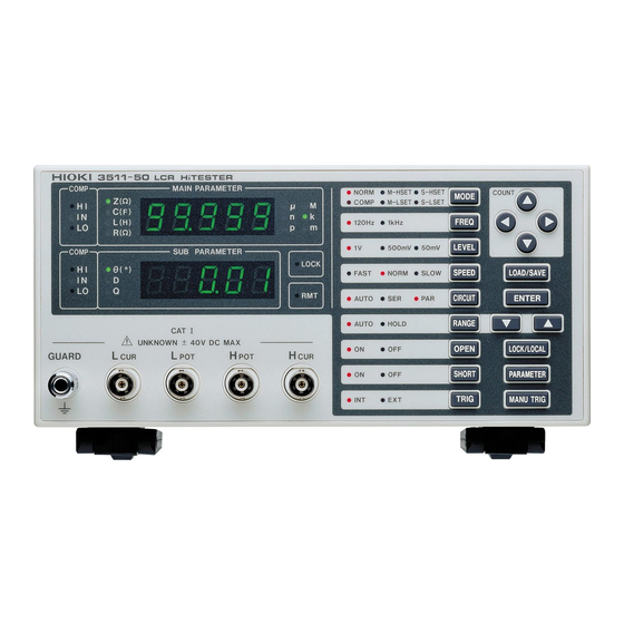
_____________________________________________________________________________________________________________ 1.3 Names and Functions of Parts 1.3.1 Front View 1. Measurement display Displays a testing parameter and corresponding measurement. 2. Status display Displays current test conditions, presettings, and other information. 3. Comparator judgment display Displays judgment in comparator mode. 4. -
Page 16: Operation Section Details
_____________________________________________________________________________________________________________ 1.3.2 Operation Section Details 1. Test mode selector key 10. Manual trigger key 2. Test frequency selector key 11. Testing parameter selector key 3. Test signal level selector key 12. LOCK/LOCAL key 4. Testing speed selector key 13. Test range selector key (up/down) 5. -
Page 17: Rear View
_____________________________________________________________________________________________________________ 1.3.3 Rear View 1. Power input socket with voltage selector Connect the supplied power cord here. 2. Power switch Turns the power for the unit on and off. 3. Optional equipment interface The optional 9518-01 GP-IB INTERFACE is connected here. 4. -
Page 18: Side View
_____________________________________________________________________________________________________________ 1.3.4 Side View 1. Stand Do not apply strong downward pressure with the stand extended. Damage CAUTION to the stand will result. ________________________________________________________________________________________________________________ 1.3 Names and Functions of Parts... -
Page 19: Chapter 2 Before Starting Measurement
Chapter 2 Before Starting Measurement 2.1 Connecting the Power Cord When a 3511-50 unit is ordered, the supply voltage is set in the factory to the value specified, which can be 100 V, 120 V, WARNING 220 V, or 240 V. -
Page 20: Connecting The Test Leads
_____________________________________________________________________________________________________________ 2.2 Connecting the Test Leads The 3511-50 has five test terminals: terminal (to which the test signal is supplied) terminal (detected voltage high terminal) terminal (detected voltage low terminal) terminal (test current detected terminal) GUARD terminal (connected to the chassis of the unit). -
Page 21: Establishing The Connections
The maximum voltage which can be applied to the test terminals of the CAUTION 3511-50 unit is 40 V DC. If a DC voltage greater than this is applied continuously, the unit may be damaged. For how to apply a DC bias voltage, refer to Section 5.2, "Supplying DC Bias."... -
Page 22: Turning The Power On And Off
_____________________________________________________________________________________________________________ 2.3 Turning the Power On and Off How to turn the power on Turn on the power switch on the rear panel. All LEDs on the front panel light. The test conditions will start off the same as they were when last the power was turned off. -
Page 23: Chapter 3 Basic Functions
Inductance (H) - Q factor Effective resistance (Ω) As shown above, the 3511-50 permits five possible combinations of testing parameters. Cycle through the combinations by repeatedly pressing Use the LED lamps to the left of the measurement display to check on selected testing parameters. -
Page 24: Setting The Test Frequency
120 Hz and 1 kHz. Use the LED lamp to the left of the key to check on a set test frequency. 3.3 Setting the Test Signal Level For the 3511-50's test signal level, you may specify 1 V, 500 mV or 50 mV. Procedure Press repeatedly to cycle through available settings: 1 V, 500 mV, and 50 mV. -
Page 25: Setting The Testing Speed
________________________________________________________________________________________________________________ 3.4 Setting the Testing Speed For testing speed, select from one of the following three levels, depending on the specific purpose. The slower the testing speed is, the more accurate are the results. FAST : Low accuracy testing is performed at high speed. NORM : The speed used for normal testing SLOW : High accuracy testing is performed slowly. -
Page 26: Setting The Equivalent Circuit Mode
You may set an equivalent circuit mode. Automatic selection is also possible. 3.5.1 Equivalent Circuit Mode The 3511-50 unit analyses the test sample in terms of a pure inductive component (L), an equivalent circuit construction composed of a pure capacitive component (C), and a pure resistive component (R), and calculates as though these components were connected in series, or alternatively connected in parallel. - Page 27 ________________________________________________________________________________________________________________ Therefore it is necessary for the user clearly to understand the setting of this test mode, in order properly to assess test samples. In general, parallel equivalent circuit mode should be used for elements which have relatively low capacitance and high impedance such as film capacitors and ceramic capacitors, since parallel resistance can cause great loss in this case;...
-
Page 28: Setting The Ranging
________________________________________________________________________________________________________________ 3.6 Setting the Ranging You may set a test range. Automatic selection is also possible. 3.6.1 Test Range A test range is set, with impedance as a reference. The range numbers, corresponding impedance ranges, and first parameter display ranges are as follows: Z-display range * R-display range... - Page 29 ________________________________________________________________________________________________________________ Z-display range * C-display range Frequency Frequency Common to 120 Hz 1 kHz 120 Hz and 1 kHz Range number Range number 009.00 to 200.00 MΩ 000.00 to 999.99 pF 00.000 to 99.999 pF 0.9000 to 9.9999 MΩ 0.0000 to 9.9999 nF 000.00 to 999.99 pF 090.00 to 999.99 kΩ...
- Page 30 ________________________________________________________________________________________________________________ To measure a parameter other than Z - i.e., C, L, or R - determine an appropriate range based on impedance. The following table presents appropriate ranges for C and L when D is equal to or smaller than 0.1 and those when θ...
- Page 31 ________________________________________________________________________________________________________________ Test range Frequency 120 Hz 1 kHz 120 Hz 1 kHz Range number Range Display range Range Display range Range Display range Range Display range 999.99 mF 100 mF 99.999 mF 200 kH 200.00 kH 20 kH 20.000 kH 013.50 mF 01.600 mF 012.00 kH...
-
Page 32: Auto Range
________________________________________________________________________________________________________________ Procedure Press to toggle between AUTO and HOLD. AUTO : The most suitable test range is set automatically. HOLD : The test range is fixed, and may only be altered manually. Use the LED lamp to the left of the key to check on a set test range. 3.6.2 Auto Range The most suitable test range is set automatically. -
Page 33: Open Circuit Compensation
With open circuit compensation set, compensated values for 120 Hz and 1 NOTE kHz are input. These are unrelated to test frequency setting conditions. The testing accuracy specified in the specification of the 3511-50 unit assumes that open circuit compensation and short circuit compensation is being performed, as appropriate. -
Page 34: Open Circuit Compensation Error
________________________________________________________________________________________________________________ If an error occurs during open circuit compensation, the unit beeps to notify you of the error. An error message appears, as shown, and compensation is aborted. Press to return the unit to normal test mode. If an error occurs, when you return to normal test mode after aborting open NOTE circuit compensation, the measurement value is not compensated for. -
Page 35: Short Circuit Compensation
With short circuit compensation set, compensated values for 120 Hz and 1 NOTE kHz are input. These are unrelated to test frequency setting conditions. The testing accuracy specified in the specification of the 3511-50 unit assumes that open circuit compensation and short circuit compensation is being performed, as appropriate. - Page 36 ________________________________________________________________________________________________________________ (2) Short circuit together the HIGH and LOW leads. In order to keep external influences as low as possible, be sure to thrust the shorting bar in all the way. As closely as possible, route the test cable during this procedure as if NOTE performing actual measurement.
-
Page 37: Short Circuit Compensation Error
________________________________________________________________________________________________________________ 3.8.2 Short Circuit Compensation Error The following are possible causes: 1. The circuit across HIGH and LOW terminals is not short. 2. The test cable is not connected correctly. 3. The impedance across the terminals exceeds 1 kΩ. 3.8.3 Canceling Short Circuit Compensation Procedures (1) Press with short circuit compensation ON. -
Page 38: Setting The Trigger Signal
When inputting the trigger signal through the EXT I/O connector: Testing is performed once, each time a negative sense pulse signal is supplied to the EXT I/O connector on the rear panel of the 3511-50. For details, refer to Section 5.1, "Testing Using EXT I/O."... -
Page 39: Chapter 4 Other Functions
Moreover, a corresponding signal can be output via the EXT I/O connector on the rear panel of the 3511-50 unit. * HI: exceeds the upper limit; IN: within upper and lower limits; LO: below the lower limit You can set comparator upper and lower limits in the first and second parameters, respectively. -
Page 40: Operation Sequence
________________________________________________________________________________________________________________ 4.1.1 Operation Sequence Set this among test conditions for executing a comparator. Normal test mode Press Automatically switches the range setting to HOLD. First parameter upper Use the COUNT setting key to set the upper limit. limit setting mode Press to acknowledge and save the set value;... - Page 41 ________________________________________________________________________________________________________________ (2) Use the COUNT setting key to change the value digit by digit. The value in the blinking digit may be altered. Navigate through the digits with the keys, and through values with the keys. To set the upper or lower limit to OFF, move the cursor to the left or right end with .
-
Page 42: Comparator Test Mode
________________________________________________________________________________________________________________ 4.1.3 Comparator Test Mode Upon completion of all upper and lower limit setting, if upper and lower limit setting is not OFF, the system enters comparator measurement mode and outputs a judgment each time a measurement is made, as a result of comparison between the measurement and the upper or lower limit. -
Page 43: Panel Save Function
After specifying a panel number in panel save mode, press instead of . The 3511-50 reverts to normal or comparator test mode without performing the panel save. Under normal conditions of use, the average life of the backup battery for NOTE the internal memory is about 6 years. -
Page 44: Panel Load Function
4.3.2 Aborting Panel Load After specifying a panel number in panel load mode, press instead of . The 3511-50 moves to panel save mode without performing the panel load. Press again. The 3511-50 reverts to normal or comparator test mode. -
Page 45: Key Lock Function
________________________________________________________________________________________________________________ 4.4 Key Lock Function When the key lock is turned on, all key switches on the front panel are disabled to protect settings. 4.4.1 Executing the Key Lock Function Press for 2 s or longer. Use the LED lamp to the right of the second parameter measurement display (SUB PARAMETER) to check on the key lock condition. -
Page 46: Various Settings Made After Switching On Power
________________________________________________________________________________________________________________ 4.5 Various Settings Made After Switching on Power Enter settings for conditions related to system reboot (initialization of all test conditions), interfaces, and beep sounds at comparator judgment immediately after switching on power. 4.5.1 Setting Screen Flow After Power ON With power turned on, screens are displayed in succession in the following order: 1. -
Page 47: Setting The Interface
3511-50 GP-IB address in the second parameter measurement display. Procedures Once power has been switched on, the 3511-50 displays version information, "rS232" in the first parameter measurement display and settings for the RS-232C interface in the second parameter measurement display for approximately 3 s. -
Page 48: Setting Beep
________________________________________________________________________________________________________________ 4.5.3 Setting Beep Set the beep to be sounded when a comparator judgment is made. The following three modes are available: 1. No beep 2. Beeps when judgment of both first and second parameters is "IN." 3. Beeps when judgment of one of the first or second parameters is not "IN." Procedures After power is switched on, the system displays the "Interface setting."... -
Page 49: Executing System Reboot
1.5 s, the Section switches to the version information screen. You can release the key when this occurs. The 3511-50 displays version information, "rESEt" in the first parameter measurement display and "no" in the second parameter measurement display. Display in the first parameter... -
Page 50: Remote Function
________________________________________________________________________________________________________________ 4.6 Remote Function 4.6.1 Remote Mode External control via an interface will place the 3511-50 in remote mode (remote control state), in which front panel key switch operations are disabled. Use the LED lamp to the right of the second parameter measurement display (SUB PARAMETER) to check on the remote mode condition. -
Page 51: The Residual Charge Protection Function
DC voltage which is constantly applied such as a superimposed DC voltage. (The maximum voltage for supply to the test terminals of the 3511-50 unit is 40 VDC.) If this is done, there is a danger of damage to the unit. - Page 52 ________________________________________________________________________________________________________________ ________________________________________________________________________________________________________________ 4.7 The Residual Charge Protection Function...
-
Page 53: Chapter 5 Applications
Compatible connector: 57-30360 (solder cup connector without rib, made by DDK) 57-30360R (solder cup connector with rib, made by DDK) RC30-36P (made by HIROSE ELECTRIC CO.,LTD.) EXT I/O Connector pin numbering (seen from 3511-50) ________________________________________________________________________________________________________________ 5.1 Testing Using EXT I/O... -
Page 54: Pinouts For The Ext I/O Connector
________________________________________________________________________________________________________________ 5.1.2 Pinouts for the EXT I/O Connector Pin number Signal line name Pin number Signal line name _____ TRIG BCD00 BCD01 BCD02 BCD03 BCD10 BCD11 BCD12 _____ BCD13 M-HI _____ _____ M-IN M-LO ____ ____ S-HI S-IN _____ ____ S-LO ______ _____... -
Page 55: Signal Lines For The Ext I/O Connector
______ (1) TRIG When the 3511-50 is set to external trigger mode, a negative logic signal is input from outside via this line. Testing is initiated once when this signal goes low level. (2) BCD00, BCD01, BCD02, BCD03 For the panel number to load, choose the ones digit. - Page 56 (9) EXT DCV, EXT COM These are terminals for supplying a power supply voltage from an external device. This enables the 3511-50 unit to be connected to an external device while maintaining the isolation. The range of power voltage which can be connected is from 5 to 24 VDC.
-
Page 57: Circuit Construction And Connections For The Ext I/O Connector
200 mA. The insulation of the signal lines is for eliminating mutual influences between the signals. Any device which is connected to the 3511-50 unit should always be properly protectively grounded. If proper connection to a protective ground is not established, there is a danger of damage to the insulation. -
Page 58: Electrical Characteristics Of The Output Signals
GND. The maximum current capacity is 100 mA. Do not connect any external circuit whose current consumption is greater than 100 mA. INT GND is grounded to the chassis of the 3511-50 unit. The output signal low level output current is a maximum of 60 mA. If a... -
Page 59: I/O Signal Timing
________________________________________________________________________________________________________________ 5.1.6 I/O Signal Timing With the test conditions for testing by the comparator having been set (with the trigger setting set to external trigger), when in this state a trigger signal is input via the EXT I/O connector, or when the key is pressed, then the decision result is output on the comparator result output signal line of the EXT I/O connector. -
Page 60: Time Taken For Testing
________________________________________________________________________________________________________________ 5.1.7 Time Taken for Testing The time taken for testing varies according to the test conditions. The following values may be used for reference. These values are all for reference only. Do not rely upon them absolutely, because NOTE the actual time taken for testing depends upon many operational conditions. - Page 61 ________________________________________________________________________________________________________________ (C) The time taken for calculation varies according as to whether or not both open circuit compensation and also short circuit compensation are performed: Open/short circuit compensation Calculation time Open and/or short circuit 1 ms compensation performed Not performed 0 ms (Allowance 0.5 ms)
-
Page 62: Supplying Dc Bias
The maximum voltage which can be applied to the test terminals of the CAUTION 3511-50 unit is 40 V DC. If a DC voltage greater than this is applied continuously, the unit may be damaged. Supplying DC bias means that a DC voltage is supplied as a bias to a sample for test whose characteristics are voltage dependent, such as an electrolytic capacitor or a ceramic capacitor. -
Page 63: How To Supply A Dc Bias Voltage
Capacitor R or L (>>Z) DC voltage Sample to be tested source 3511-50 GUARD DC Bias Voltage Circuit Use a resistance (R) or inductance (L) which has a large enough impedance with reference to the sample under test (Z). Use a capacitor (C) which has a small enough impedance (i.e., a large enough capacitance) with reference to the sample under test (Z). -
Page 64: How To Supply A Dc Bias Current
DC current Sample to be tested ↑ source 3511-50 DC Bias Current Circuit Use a choke coil (CH) which has a large enough impedance with reference to the sample under test (Z). Use a capacitor (C) which has a small enough impedance (i.e., a large enough capacitance) with reference to the sample under test (Z). -
Page 65: 9442 Printer (Option)
Change the settings of the software dip switches (DIP SW) to use the 9442 for the 3511-50. The 9442 is shipped with the function settings for use with the HIOKI CAUTION 3166 CLAMP ON POWER HiTESTER. Before using, always change the settings of the DIP switches. - Page 66 ________________________________________________________________________________________________________________ Software DIP SW1 : Use these settings for the 3511-50 Switch No. Function ON (ON LINE) OFF (FEED) Input method Parallel Serial Printing speed High Auto loading Enable Carriage return CR function Carriage return and line feed DIP SW setting...
-
Page 67: Connection Method
To avoid electrocution, turn off the power to all devices before WARNING plugging or unplugging any cablesor peripherals. (1) Set the 9442 PRINTER referring to Section 5.3.1, "Preparation." (2) Connect the 9444 CONNECTION CABLE between the main unit and the printer. 3511-50 9442 Frame Frame ________________________________________________________________________________________________________________... -
Page 68: Printing Results
________________________________________________________________________________________________________________ 5.3.3 Printing Results When the external trigger is set, the test values are printed out after the test is completed. 1. Normal test 2. Comparator operating ________________________________________________________________________________________________________________ 5.3 9442 PRINTER (Option) -
Page 69: Testing High Impedance Elements
________________________________________________________________________________________________________________ 5.4 Testing High Impedance Elements The measured value obtained when testing a high impedance element (such as, for example, a resistor with resistance higher than 100 kΩ) is sometimes unreliable, because such an element is vulnerable to the effects of external interference and the like. -
Page 70: Testing An Element In A Circuit
________________________________________________________________________________________________________________ 5.5 Testing an Element in a Circuit Test an element in a circuit after guarding. Referring to the following figure, when measuring a resistance value for the resistor R , even if the tips of the two probes are contacted against the ends of the resistor R , considering the sum of the current flowing through the resistor R... -
Page 71: External Interference
________________________________________________________________________________________________________________ 5.6 External Interference The 3511-50 is designed to be resistant to errors caused by interference from the test cables or the power supply line. However, if the level of the interference is particularly large, this can cause measurement errors or faulty operation. -
Page 72: Countermeasures Against Noise From The Test Cables
AC power inlet of the 3511-50 unit, so as to suppress noise from the power supply line. Further benefit can often be obtained by fitting another anti- interference ferrite core on to the power cord at its other end, as close as possible to the plug which connects to the power supply outlet. -
Page 73: Chapter6 Rs-232C Interface
________________________________________________________________________________________________________________ Chapter6 RS-232C Interface 6.1 Overview 6.1.1 Introduction to the RS-232C Interface It is possible to control all the functions of the 3511-50 (except for powering on and off) via the RS-232C bus. ________________________________________________________________________________________________________________ 6.1 Overview... -
Page 74: Specifications
Output voltage levels ON 5 V to 9 V OFF 9 V to -5 V RS-232C connector The connector on the 3511-50 is for terminal (DTE). Connect the RS-232C cable. 1 2 3 4 5 6 7 8 9 RS-232C interface connector pin assignments... -
Page 75: Connecting Method
Always fix the screws to connect the RS-232C cable. When connecting the controller (DTE), use a cross cable which meets the connector specifications of both sides of the 3511-50 and the controller. Commands that contain data must be input in the specified data format. -
Page 76: Handshake
________________________________________________________________________________________________________________ 6.2.1 Handshake Buffer flow control (1) Controls when receiving When the receiving buffer is more than 85 % full, CA (RTS) is set to OFF to indicate to the controller that the empty buffer capacity is low. Processing of data in the buffer continues, and when the receiving buffer is less than 25 % full, CA (RTS) is set to ON to indicate to the controller that there is ample buffer capacity. -
Page 77: Operation
________________________________________________________________________________________________________________ 6.3 Operation 6.3.1 Communication Methods by the RS-232C In order to control the 3511-50 by the RS-232C, there are several kinds of messages. Of these, program messages are those received by the 3511-50 from the computer, while response messages are those sent from the 3511-50 to the computer. -
Page 78: Message Format
However, any one of "FREQU", or "FRE" is wrong and will generate an error. 6.3.4 Response Messages It represents the response message for query messages from the 3511-50. Response messages generated by the 3511-50 are in long form and in upper case letters. Example :FREQUENCY 1000 (Current frequency is 1 kHz.) -
Page 79: Headers
________________________________________________________________________________________________________________ 6.4 Headers (1) Program message headers There are three types of header: simple headers, compound headers, and particular headers. Simple header A header consisting of a single word beginning with a letter. Examples etc. :HEADer Compound header A header consisting of a sequence of words separated by colons. , etc. -
Page 80: Data Formats
Unsigned numbers are taken as positive. Further, if the accuracy of a numerical value exceeds the limit which the 3511-50 can deal, it is rounded off (5 and above is rounded up; 4 and below is rounded down). -
Page 81: Delimiters
The term "delimiter" is used to refer to the following possibility for separating data sequences. The 3511-50 recognizes a carriage return plus linefeed (CR+LF) as delimiters. The 3511-50 only begins to analyze a command after recognizing the delimiter. NOTE 6.7 Separators (1) Message unit separator A semicolon (;) is used as a message unit separator when it is desired to set... -
Page 82: Abbreviation Of Compound Commands
Messages with particular headers can be executed without relation to the current path. Further, they have no effect upon the current path. With the 3511-50, there are 5 possible current paths: :BEEPer: :COMParator:... -
Page 83: Output Queue
The output queue is also cleared when the power is turned off and turned on again. The 3511-50 has an output queue of 300 bytes capacity. If the response messages overflow this limit of 300 bytes, a query error is generated, and the output queue is cleared. -
Page 84: Event Registers
________________________________________________________________________________________________________________ 6.11 Event Registers The 3511-50 includes three 8 bit event registers. It is possible to determine the status of the unit by reading these registers. The event register is cleared in the following situations: When a "*CLS" command is executed. - Page 85 ________________________________________________________________________________________________________________ (2) Event status registers 0 and 1 (ESR0 and ESR1) Event Status Register 0 (ESR0) Bit Assignments Bit 7 Compensation data measurement completed Bit 6 Second parameter range overflow Bit 5 Second parameter range underflow Bit 4 First parameter range overflow Bit 3 First parameter range und e rflow Bit 2...
-
Page 86: Command Reference
________________________________________________________________________________________________________________ 6.12 Command Reference 6.12.1 Command Summary Particular commands Command Explanation page Clears event register. *CLS Queries standard event status register (SESR). *ESR? Queries device ID. *IDN? Device initialization. *RST Performs sampling once. *TRG Queries the result of the self-test. *TST? Waits until all execution is fully completed. - Page 87 ________________________________________________________________________________________________________________ Command Function page Communication error confirmation :ERRor? Queries the RS-232C error. Event register :ESR0? Queries event status register 0. :ESR1? Queries event status register 1. Test frequency function :FREQuency Sets the test frequency. :FREQuency? Queries the test frequency. Headers :HEADer Enables and disables headers for the response message.
-
Page 88: Format Of Command Explanations
Note that all transmission messages are expressed in a "short form." Specifies what types of error may occur. Error On the 3511-50, internal processing may involve a delay of 20 ms to 500 ms NOTE maximum from command receipt to start of analysis. -
Page 89: Particular Commands
No header is affixed to the response message. First field Manufacturer's name Second field Model name Third field Fixed for fifty Fourth field Software version Example HIOKI,3511,50,V01.00 Response Error If the response message is longer than 300 bytes, a query error is generated. ________________________________________________________________________________________________________________ 6.14 Particular Commands... - Page 90 ________________________________________________________________________________________________________________ *RST Performs device initial setting. Syntax *RST Function Resets the 3511-50. The items which are reset are listed below. Impedance (Z), phase angle (θ) Test parameters 1 kHz Test frequency Test signal level AUTO Test range AUTO Equivalent circuit mode...
- Page 91 Syntax *TST? Function Performs the self test of the 3511-50, and returns the result thereof as a numerical value in NR1 format between 0 and 3. No header is affixed to the response message. Bit 0: A ROM error occurred.
-
Page 92: Commands Specific To The 3511-50
________________________________________________________________________________________________________________ 6.15 Commands Specific to the 3511-50 :BEEPer:COMParator Sets the beep sound for the comparator. Syntax :BEEPer:COMParator <data> <data> IN/NG/OFF (character data) Function Sets the beep sound produced when the comparator makes decisions. IN: When the comparator result is within limits, a beep sound is emitted. - Page 93 Error If <data> is other than character data described above, an execution error occurs. Executing this command while the open or short circuit compensation is performed generates an execution error. ________________________________________________________________________________________________________________ 6.15 Commands Specific to the 3511-50...
- Page 94 Returns whether the equivalent circuit mode is automatically set as character data. Example Response ":CIRCUIT:AUTO ON" If headers are on If headers are off "ON" Error If the response message is longer than 300 bytes, a query error is generated. ________________________________________________________________________________________________________________ 6.15 Commands Specific to the 3511-50...
- Page 95 Error If <data> is other than character data or numerical value described above, an execution error occurs. Executing this command while the open or short circuit compensation is performed generates an execution error. ________________________________________________________________________________________________________________ 6.15 Commands Specific to the 3511-50...
- Page 96 Example Response :COMPARATOR:SLIMIT 11234,12345 If headers are on 11234,12345 If headers are off Error If the response message is longer than 300 bytes, a query error occurs. ________________________________________________________________________________________________________________ 6.15 Commands Specific to the 3511-50...
- Page 97 The open circuit compensation function is set to ON. Error If <data> is other than character data described above, an execution error occurs. Executing this command while the comparator function is performed generates an execution error. ________________________________________________________________________________________________________________ 6.15 Commands Specific to the 3511-50...
- Page 98 :CORRECTION:SHORT ON If headers are on If headers are off The open circuit compensation function has been enabled. Error If the response message is longer than 300 bytes, a query error is generated. ________________________________________________________________________________________________________________ 6.15 Commands Specific to the 3511-50...
- Page 99 0 Unused Event status register 0 (ESR0) Example Response Bit 2 of ESR0 has been set to 1. Error If the response message is longer than 300 bytes, a query error is generated. ________________________________________________________________________________________________________________ 6.15 Commands Specific to the 3511-50...
- Page 100 If headers are on If headers are off 1000 The test frequency has been set to 1 kHz. Error If the response message is longer than 300 bytes, a query error is generated. ________________________________________________________________________________________________________________ 6.15 Commands Specific to the 3511-50...
- Page 101 Syntax :HEADer <data> <data> ON/OFF (character data) Function Sets whether or not the 3511-50 will prefix headers to its response messages. When powering on, <data> is initially set to ON. Example :HEADer ON Transmission Headers are prefixed to response messages.
- Page 102 If the panel number in which the settings have not been saved is selected, an execution error occurs. Executing this command while the open or short circuit compensation is performed generates an execution error. ________________________________________________________________________________________________________________ 6.15 Commands Specific to the 3511-50...
- Page 103 The decision result of the first parameter is IN, and that of the second parameter is LO. Error If the response message is longer than 300 bytes, a query error is generated. Executing this command while the open or short circuit compensation is performed generates an execution error. ________________________________________________________________________________________________________________ 6.15 Commands Specific to the 3511-50...
- Page 104 If headers are off The first parameter has been set to impedance, and the second parameter has been set to phase angle. Error If the response message is longer than 300 bytes, a query error occurs. ________________________________________________________________________________________________________________ 6.15 Commands Specific to the 3511-50...
- Page 105 The test range is set to 1 kΩ. Error If <data> is other than numerical value described above, an execution error occurs. Executing this command while the open or short circuit compensation is performed generates an execution error. ________________________________________________________________________________________________________________ 6.15 Commands Specific to the 3511-50...
- Page 106 Returns whether the test range is automatically set as character data. Example Response If headers are on :RANGE:AUTO ON If headers are off Error If the response message is longer than 300 bytes, a query error is generated. ________________________________________________________________________________________________________________ 6.15 Commands Specific to the 3511-50...
- Page 107 :SPEEd NORMal Transmission Error If <data> is other than character data described above, an execution error occurs. Executing this command while the open or short circuit compensation is performed generates an execution error. ________________________________________________________________________________________________________________ 6.15 Commands Specific to the 3511-50...
- Page 108 If headers are on :TRIGGER INTERNAL INTERNAL If headers are off The trigger mode has been set to internal triggering. Error If the response message is longer than 300 bytes, a query error is generated. ________________________________________________________________________________________________________________ 6.15 Commands Specific to the 3511-50...
- Page 109 AB-1234 If headers are off Error If the response message is longer than 300 bytes, a query error is generated. If this command is executed without user ID setting, an execution error occurs. ________________________________________________________________________________________________________________ 6.15 Commands Specific to the 3511-50...
-
Page 110: Initialization Items
________________________________________________________________________________________________________________ 6.16 Initialization Items The following table shows which items are initialized and which not, under various conditions. Initialization method Powering *RST *CLS command command Item RS-232C communication conditions Device specific functions (ranges etc.) *1 Output queue Input buffer Event registers Current path Headers on/off Measurement resister... -
Page 111: Sample Programs
All commands in the sample programs are used in the short form. (1) Open- and short-circuit compensation Summary This program carries out open- and short-circuit compensation on the 3511-50. Program List 10 OPEN "COM1:9600,N,8,1,LF" FOR RANDOM AS #1 20 PRINT #1, ":HEAD OFF"... - Page 112 Z 1.0001E+03, PHASE 0.26 (3) Saving the 3511-50 settings using the panel save function Summary This program makes the settings for the 3511-50 and saves the settings to the panel number 1 as "TEST1." Program List 10 OPEN "COM1:9600,N,8,1,LF" FOR RANDOM AS #1 20 PRINT #1,":PAR 1"...
- Page 113 ________________________________________________________________________________________________________________ Enables the beep sound by key input. The beep sounds when the comparator result is NG. Save the settings to the panel number 1. Close the RS-232C circuit file. (4) Carrying out comparator testing This program first makes the comparator settings. At the end of testing, it displays the numbers of the samples which were outside the comparator limit.
- Page 114 ________________________________________________________________________________________________________________ Program comments Line Comment Open the RS-232C circuit file. Set displayed parameters to C-D. Select external trigger mode. Switch off headers for the response message. Set the test frequency to 120 Hz. µ Set the test range to range 5 (1.45 Set the test voltage to 1 V.
-
Page 115: Troubleshooting
Due to the response message being produced at the instant that the query differs from the display 3511-50 receives the query, there is a possibility that it may not on the front panel of the 3511- agree with the display at the instant that the controller reads it in. - Page 116 ________________________________________________________________________________________________________________ ________________________________________________________________________________________________________________ 6.18 Troubleshooting...
-
Page 117: Chapter 7 Maintenance, Adjustment, And Disposal
Under normal conditions of use, the average life of the backup battery is about 6 years. Do not block the ventilation openings in the case of the 3511-50 unit with cloth or the like. If you do so, there is a danger of damaging the unit by overheating or even of causing a fire. -
Page 118: How To Change The Power Supply Fuse And Change The Power Supply Voltage
7.2 How to Change the Power Supply Fuse and Change the Power Supply Voltage The power supply fuse for the 3511-50 unit, and the power supply voltage selector, are housed in the power input socket on the rear panel. When changing the power supply fuse or changing the power... - Page 119 ________________________________________________________________________________________________________________ Changing the fuse, or altering the power supply voltage setting (1) Turn the power switch off, and then remove the power cord. (2) Using a slot head screwdriver or the like, bias sideways the catch which holds the fuse box into the power input socket as shown in the figure, and then remove the fuse box.
- Page 120 ________________________________________________________________________________________________________________ Illustrations showing changing the power supply fuse and changing the power supply voltage: AC socket Screwdriver Pry the catch with a slot head screwdriver or the like and remove the fuse box. Fuse box When changing the power supply fuse: When altering the power supply voltage setting: Voltage selector Fuse...
-
Page 121: Shipping The Unit
For the method of system reset, see Section 4.5.4, "Executing System Reboot." If any of the following should occur, stop using the unit, disconnect the power cord and input cables, and contact your dealer or HIOKI representative. If you are certain that the unit is damaged. -
Page 122: Disposing Of The Unit
________________________________________________________________________________________________________________ 7.5 Disposing of the Unit A lithium battery is used in the 3511-50 as a power source for recording test conditions. To avoid electrocution, turn off the power switch and disconnect WARNING the power cord and measurement cables before removing the lithium battery. - Page 123 ________________________________________________________________________________________________________________ 3. The battery holder is located in the position illustrated on the left. Insert a Lithium battery pointed tool, such as the tip of a tweezers, between the battery and the battery holder, and lift the battery to remove it. ________________________________________________________________________________________________________________ 7.5 Disposing of the Unit...
- Page 124 ________________________________________________________________________________________________________________ ________________________________________________________________________________________________________________ 7.5 Disposing of the Unit...
-
Page 125: Chapter 8 Specifications
________________________________________________________________________________________________________________ Chapter 8 Specifications 8.1 General Specifications Test parameters |Z| (Impedance) θ (Phase angle) C (Capacitance) D (Loss coefficient, tan δ) L (Inductance) Q (Quality factor) R (Resistance) Test frequencies (FREQ) 120 Hz, 1 kHz (Frequency accuracy: 0.01% or less) 50 Ω... - Page 126 ________________________________________________________________________________________________________________ Zero compensation Open circuit compensation: Correction of residual admittance between the measurement terminals of the fixture. Operation is possible when, with the terminals open circuit, the impedance is at least 1 kΩ. Short circuit compensation: Correction of residual impedance between the measurement terminals of the fixture.
- Page 127 ________________________________________________________________________________________________________________ Options 9140 4-TERMINAL PROBE 9143 PINCHER PROBE 9261 TEST FIXTURE 9262 TEST FIXTURE (direct connection type) 9263 SMD TEST FIXTURE (direct connection type) 9268 DC BIAS VOLTAGE UNIT 9269 DC BIAS CURRENT UNIT 9165 CONNECTION CORD (for 9268, 9269/BNC-BNC/1.5 m) 9166 CONNECTION CORD (for 9268, 9269/BNC-clip/1.5 m) 9442 PRINTER 9443-01 AC ADAPTER (for printer, for Japan)
-
Page 128: Testing Parameters And Calculation Equations
8.2 Testing Parameters and Calculation Equations Normal circuit elements etc. are assessed with regard to their characteristics in terms of their impedance Z. The 3511-50 for subjects such circuit components to an alternating current signal at a certain test frequency, measures their voltage and current vectors, and from these values obtains the impedance Z and the phase angle θ... - Page 129 I which flows through the test sample at this time, the phase angle θ between this voltage V and this current I, and the angular velocity ω which corresponds to the test frequency, the 3511-50 can calculate the following components by using the calculation equations shown: The phase angle θ...
-
Page 130: Test Accuracy
When C = 160 nF, D = 0.2, test frequency = 1 kHz, signal level = 1 V, and speed = SLOW: (1) Find Z- θ (this is possible with Z- θ measurements for 3511-50). θ = tan (1/D) = 78.69( ) Z = (1/ωC) x (1/sin θ... - Page 131 ________________________________________________________________________________________________________________ The coefficients corresponding to the following settings are calculated from each table an d mu s t be multiplied (4 mu s t be added) to the basic accuracy. 1. Test signal level 50 mV 500 mV Coefficient 2. Test speed coefficient FAST NORMAL SLOW...
- Page 132 ________________________________________________________________________________________________________________ Accuracy table Range No. Range No. Z- θ (Z、L、R) (2.00+0.11XZ (2.00+1.00XfXL (2.00+0.16XR (1.70+30/(fXC θ (0.70+0.08XZ (0.0120+0.0100XfXL (0.0120+0.25/(fXC (0.15+0.16XZ (0.17+1.17XfXL (0.15+0.20XR (0.17+30/(fXC θ (0.10+0.09XZ (0.0020+0.0110XfXL (0.0020+0.264/(fXC 0.30% 0.34% 0.34% 0.34% θ 0.19 0.0036 0.0036 0.14% 0.16% 0.16% 0.16% θ 0.10v 0.0020 0.0020 0.11%...
-
Page 133: Chapter 9 Options
This tweezer type probe is very convenient for testing samples such as chips. The impedance range which can be measured by the 3511-50 using this probe varies according to the frequencies. When using a probe, it may happen that the values obtained vary because the NOTE contact resistance is altering due to alterations in the pinch pressure exerted. - Page 134 ________________________________________________________________________________________________________________ 9261 TEST FIXTURE Samples to be tested can be comparatively easily loaded into and removed from this type of fixture. 9262 TEST FIXTURE 9263 SMD TEST FIXTURE This is very convenient for testing samples such as chips. 9268 DC BIAS VOLTAGE UNIT Maximum input voltage: 40 VDC ________________________________________________________________________________________________________________...
- Page 135 ________________________________________________________________________________________________________________ 9269 DC BIAS CURRENT UNIT Maximum input voltage: 2 A 9442 PRINTER The test values can be printed out. To use the printer, the following optional units are necessary. 9443-01 AC ADAPTER (for printer, for Japan) 9443-02 AC ADAPTER (for printer, for EU) 9443-03 AC ADAPTER (for printer, for U.S.A) 9444 CONNECTION CABLE 1196 RECORDING PAPER...
- Page 136 ________________________________________________________________________________________________________________ ________________________________________________________________________________________________________________...
- Page 139 All reasonable care has been taken in the production of this manual, but if you find any points which are unclear or in error, please contact your supplier or the Sales and Marketing International Department at HIOKI headquarters. In the interests of product development, the contents of this manual are subject to revision without prior notice.
- Page 140 2000-12 改訂 枠消す HEAD OFFICE 81 Koizumi, Ueda, Nagano 386-1192, Japan TEL +81-268-28-0562 / FAX +81-268-28-0568 E-mail: os-com@hioki.co.jp HIOKI USA CORPORATION 6 Corporate Drive, Cranbury, NJ 08512, USA TEL +1-609-409-9109 / FAX +1-609-409-9108 3511C981-02 02-07H Printed on recycled paper...
Need help?
Do you have a question about the 3511-50 and is the answer not in the manual?
Questions and answers