Table of Contents
Advertisement
Advertisement
Table of Contents

Related Manuals for Hioki 3541


Summary of Contents for Hioki 3541
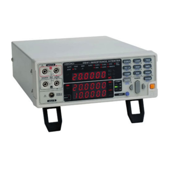
- Page 1 INSTRUCTION MANUAL 3541 RESISTANCE HiTESTER...
-
Page 3: Table Of Contents
Contents Contents Introduction.................1 Inspection ...................1 Safety Information ..............2 Operating Precautions..............4 Chapter 1 Overview ___________________________________ 9 Product Overview............9 Features ................9 Names and Functions of Parts ........11 Chapter 2 Measurement Preparations___________________ 17 Procedure..............17 Connecting the Power Cord ........18 Connecting the Test Leads .........19 Connecting the Temperature Probe......21 Connecting an Analog Output Thermometer ....22 Connecting the Temperature HiTester via RS-232C ..23... - Page 4 Contents Chapter 5 Applied Function Settings____________________ 45 Comparator Measurement Function......45 BIN Measurement Function........51 Averaging Function............. 57 Temperature Correction Function (TC) ...... 58 Temperature Conversion Function (∆t) ...... 60 Statistical Calculation Functions......... 62 Offset Voltage Compensation (OVC) ......65 Self-Calibration ............
- Page 5 Contents Chapter 8 RS-232C/GP-IB Interfaces ____________________ 95 Overview and Features ..........95 Specifications ..............96 8.2.1 RS-232C Specifications ..........96 8.2.2 GP-IB Specifications .............96 Connections and Protocol Selection ......97 8.3.1 Attaching the Connector ..........97 8.3.2 Communications Protocol Selection ......99 Communication Methods ..........100 8.4.1 Message Format ............100 8.4.2 Output Queue and Input Buffer ........105...
- Page 6 Contents Appendix 5 JEC 2137-Compliant Resistance Measurement of Inductive Machines........175 Appendix 6 Test Lead Options .......... 176 Appendix 7 Rack Mounting ..........178 Appendix 8 Dimensional Diagram ........180 Index ______________________________________ i...
-
Page 7: Introduction
Introduction Introduction Thank you for purchasing the HIOKI “Model 3541 RESISTANCE HiTESTER". To obtain maximum performance from the instrument, please read this manual carefully, and keep it handy for future reference. Inspection Confirming When you receive the instrument, inspect it carefully to ensure that no... -
Page 8: Safety Information
Safety Information Safety Information This instrument is designed to comply with IEC 61010 Safety Standards, and has been thoroughly tested for safety prior to shipment. However, mishandling during use could result in injury or death, as well as damage to the instrument. Be certain that you understand the instructions and precautions in the manual before use. - Page 9 Safety Information Overvoltage Categories (CAT) This instrument complies with CAT II (power supply section) safety requirements. To ensure safe operation of measurement instruments, IEC 60664 establishes safety standards for various electrical environments, categorized as CAT I to CAT IV, and called overvoltage categories. These are defined as follows.
-
Page 10: Operating Precautions
• Before using the instrument the first time, verify that it operates normally to ensure that the no damage occurred during storage or shipping. If you find any damage, contact your dealer or Hioki representative. • Before using the instrument, make sure that the insulation on the probes and cables is undamaged and that no bare conductors are improperly exposed. - Page 11 Operating Precautions Handling the Cords and Probes • Avoid stepping on or pinching cables, which could damage the cable insulation. • To avoid breaking the cables and test leads, do not bend or pull them. • To avoid damaging the power cord, grasp the plug, not the cord, when unplugging it from the power outlet.
- Page 12 Operating Precautions Before Connecting and Powering On Power and Grounding • Before turning the instrument on, make sure the supply voltage matches that indicated on the its power connector. Connection to an improper supply voltage may damage the instrument and present an electrical hazard.
- Page 13 (between terminal contacts). Do not apply voltage exceeding this range. • Battery internal resistance cannot be measured with this instrument. It will sustain damage. To measure battery internal resistance, we recommend the HIOKI 3550, 3551 and 3555 BATTERY HiTESTERs or the 3560 AC m HiTESTER. Ω...
- Page 14 • When measuring objects with a large inductance (L-content) such as power transformers, the measured value may be unstable. In such cases, contact your dealer or Hioki representative. Using the Temperature Probe • Holding the temperature probe in a bare hand can cause enough noise pickup to destabilize measurements.
-
Page 15: Chapter 1 Overview
Chapter 1 Overview 1.1 Product Overview The 3541 employs a four-terminal measurement method that is ideal for measuring the resistance of motor and transformer windings, relay/ switch and connector contacts, PCB patterns, chip inductor DC resistance and for ohmmeter shipping inspection tests. The instrument... - Page 16 Equipped with GP-IB and RS-232C Standard Interfaces Full remote control is available through the GP-IB and RS-232C interfaces. Prints Measurement Values and Calculation Results (Printer Optional) Connect the optional HIOKI 9670 PRINTER to print out measurement values and statistical calculation results.
-
Page 17: Names And Functions Of Parts
1.3 Names and Functions of Parts 1.3 Names and Functions of Parts Front Panel Input Terminals INPUT A Connect the supplied 9287 CLIP TYPE LEAD or optional measurement leads. Display ❖ Connections: (Page 19) Operating Keys Main Display ❖ (Page 13) ❖... -
Page 18: Main Display
1.3 Names and Functions of Parts Main Display Displays the current measurement function, measured value (while measuring) or setting item (while setting). (Lower row) (Upper row) Lit when the Statistical Calculation STAT Lit when measuring with Auto-Ranging. AUTO function is enabled. FAST, MED, SLOW1, SLOW2 Lit when the Temperature Correction The selected sampling rate is lit. - Page 19 1.3 Names and Functions of Parts Operating Keys To use a function marked on a key, just press the key. Use as ten-keys to enter numerical To use a function printed under values. a key (blue letter), press the (Numerical values SHIFT key first (and confirm can be used with the the SHIFT lamp is lit),...
- Page 20 1.3 Names and Functions of Parts Rear Panel RS-232C Connector Connection for the printer or RS-232C Power Inlet interface. Connect the supplied power cord here. ❖ Printer (Page 88), RS-232C (Page 97), ❖ Temperature HiTester (Page 23) (Page 18) EXT I/O Connector GP-IB Connector TC SENSOR Jack Connect here to control...
- Page 21 1.3 Names and Functions of Parts Menu Display Sequence (SHIFT Lamp lit) The Menu display appears. (Main Display) The up/down RANGE key changes the setting shown on the Sub Display. Zero-Adjust Clear Temperature Interface Self-Calibration Setting Display Correction/Conversion Selection Display Setting Display ❖...
- Page 22 1.3 Names and Functions of Parts...
-
Page 23: Measurement Preparations
2.1 Procedure Measurement Chapter 2 Preparations 2.1 Procedure (Page 18) (Page 19) Front Panel Rear Panel Temperature measurement Temperature measurement via (Page 24) Temperature Probe (Page 21) RS-232C interface (3444/3445) Analog Output Thermometer (Page 22) (Page 23) Connecting the power cord. Connect the test leads to the instrument. -
Page 24: Connecting The Power Cord
2.2 Connecting the Power Cord 2.2 Connecting the Power Cord • Before turning the instrument on, make sure the supply voltage matches that indicated on the its power connector. Connection to an improper supply voltage may damage the instrument and present an electrical hazard. -
Page 25: Connecting The Test Leads
This instrument is equipped with an input with four separate banana- jack terminals (INPUT A) and another input with a multipolar socket (INPUT B). The supplied Model 9287 CLIP TYPE LEAD and Hioki's various optional measurement leads connect to the INPUT A terminals. ❖... - Page 26 2.3 Connecting the Test Leads Connecting to the terminals _____________________________________ INPUT A Connection Method Front Panel Connect four-terminal test leads such as the 9287 CLIP TYPE LEAD to INPUT A. Black Plug the mark on the red lead into the marked jack on the instrument, and plug the mark on the black lead...
-
Page 27: Connecting The Temperature Probe
2.4 Connecting the Temperature Probe 2.4 Connecting the Temperature Probe Do not apply voltage to the TC SENSOR jack, to avoid electric shock accidents or damage to the instrument. To avoid damage to the instrument or temperature probe, observe the following precautions: •... -
Page 28: Connecting An Analog Output Thermometer
The connection requires a standard 3.5-mm monaural mini-phone plug. The following TEMPERATURE HiTESTERs are available from Hioki: • The Model 3444 TEMPERATURE HiTESTER (for long-focus, narrow-visual-field measurements) + 3909 INTERFACE PACK • The Model 3445 TEMPERATURE HiTESTER (for short-focus, microscopic surface measurements) + 3909 INTERFACE PACK Note that thermometer circuit is grounded. -
Page 29: Connecting The Temperature Hitester Via Rs-232C
2.6 Connecting the Temperature HiTester via RS-232C 2.6 Connecting the Temperature HiTester via RS-232C Using the RS-232C interface, you can connect the HIOKI 3444/ 3445 TEMPERATURE HiTESTERs to the unit for temperature measurement. The connection requires the 9637 RS-232C CABLE (option). -
Page 30: Turning The Power On And Off
2.7 Turning the Power On and Off 2.7 Turning the Power On and Off Turning the Power On Turn the POWER switch ON ( | ). After Power-On • The model name, software version, line frequency selection and interface selection appear before the measurement state is displayed. -
Page 31: Selecting The Line Frequency
2.8 Selecting the Line Frequency 2.8 Selecting the Line Frequency (SHIFT Lamp lit) The Menu display appears. Select the Line Frequency setting display. (Refer to the Menu displays (Page 15)) (Main Display) Select the frequency of the AC mains supply being used. (Sub Display) To select the measurement terminals immediately after selecting the line... -
Page 32: Selecting The Measurement Terminals
2.9 Selecting the Measurement Terminals 2.9 Selecting the Measurement Terminals When continuing setting from (SHIFT Lamp lit) Line Frequency Selection, skip this step. The Menu display appears. Select the Measurement Terminal selection display. (Refer to the Menu displays (Page 15)) (Main Display) When setting immediately after Line Frequency setting, press... - Page 33 2.9 Selecting the Measurement Terminals About Input Terminal Usage______________________________________ The factory-default input terminal selection is INPUT A, the four (banana jack) terminals, enabling use of Hioki's various test-lead options. INPUT A A 10 nF capacitor is connected between the H-L terminals of INPUT A.
- Page 34 2.9 Selecting the Measurement Terminals...
-
Page 35: Chapter 3 Measurement
3.1 Resistance Measurement display appears. Chapter 3 Measurement Before starting measurement, please read Safety Information (Page 2) and Chapter 2 Measurement Preparations (Page 17). 3.1 Resistance Measurement The following example describes the resistance measurement process. Example: Measuring a 10 mΩ shunt resistance Required 10 mΩ... - Page 36 3.1 Resistance Measurement Set the sampling rate to SLOW2. ❖ 4.4 Sampling Rate Setting (Page 42) (Main Display) The lit position moves with each key-press. SLOW2 lit) Enable Offset Voltage Compensation. ❖ 5.7 Offset Voltage Compensation (OVC) (Page 65) (Main Display) lit) Execute zero-adjust.
-
Page 37: Temperature Measurement (Temperature Correction & Conversion)
3.2 Temperature Measurement (Temperature Correction & Conversion) 3.2 Temperature Measurement (Temperature Correction & Conversion) Temperature Using the temperature at time of measurement, temperature Correction correction is applied to convert the measured resistance value to the value it would have at a specified reference temperature. ❖... - Page 38 3.2 Temperature Measurement (Temperature Correction & Conversion) Temperature Measurement Place the 9451 TEMPERATURE PROBE near the point to measure, and read the temperature. (Main Display) Read the current temperature. Temperature Correction & Conversion Settings Select resistance or low power measurement, and select temperature correction or conversion.
- Page 39 3.2 Temperature Measurement (Temperature Correction & Conversion) Temperature Measurement with Analog Input (Radiation Thermometer) Preparations Connect the test leads and the analog output thermometer (radiation thermometer) to the instrument, and turn it on. ❖ 2.3 Connecting the Test Leads (Page 19), 2.4 Connecting the Temperature Probe (Page 21) Select the appropriate line frequency and measurement terminals.
- Page 40 3.2 Temperature Measurement (Temperature Correction & Conversion) Measurement Read the value. (Main Display) The displayed value is calculated by the following expression. – – ---------------- --------------------------- - • (Input Voltage) + – – アナログ入力電圧 Analog Input Voltage Temperature measurement via RS-232C interface (using the 3444/3445 ______________________ TEMPERATURE HiTESTER+ 3909 INTERFACE PACK)
- Page 41 3.2 Temperature Measurement (Temperature Correction & Conversion) Temperature Measurement Read the value. (Main Display) • Temperature measurement via the RS-232C interface is possible only with the 3444/3445 TEMPERATURE HiTESTERs. • When you set the temperature sensor type to "rS", power to the 3444/ 3445 will be switched ON automatically.
- Page 42 3.2 Temperature Measurement (Temperature Correction & Conversion)
-
Page 43: Basic Function Settings
4.1 Selecting Measurement Functions Basic Function Chapter 4 Settings 4.1 Selecting Measurement Functions Settings Select the Resistance, Low-Power Resistance or Temperature measurement function. Switching the Measurement Function Confirm the SHIFT lamp is not lit. Switches the displayed measurement function. Each key-press switches the measurement function. (Main Display) Resistance Measurement display Ω... -
Page 44: Measurement Range Setting
4.2 Measurement Range Setting 4.2 Measurement Range Setting Settings Select the measurement range. Auto-ranging (the AUTO range) can also be selected. Manual Range Setting Select the range to use. (AUTO off) The decimal point location and unit indicator change with each key- press. - Page 45 4.2 Measurement Range Setting Resistance Measurement Low Power Resistance Function Measurement Function Range Displayed Values Measurement Open-Terminal Measurement Open-Terminal Current Voltage Current Voltage* Ω −−−−−−−−− −−−−−−−−− 20mΩ 20.0000 to -0.2000 m 1 A ±5% 5 Vmax −−−−−−−−− −−−−−−−−− 200mΩ 200.000 to -2.000 Ω...
-
Page 46: Zero-Adjust Function
4.3 Zero-Adjust Function 4.3 Zero-Adjust Function Settings nullify instrument's offset voltage effects thermoelectromotive force, perform zero adjustment before measuring. Specified measurement accuracy applies only after zero adjustment has been performed. Executing Zero Adjustment Short the test leads together. Proper zero adjustment is not possible with incorrect wiring. - Page 47 4.3 Zero-Adjust Function • Zero adjustment should be executed in each range to be used. When auto-ranging is selected, zero adjustment is executed in all ranges. • When zero adjustment is executed with auto-ranging, correct zero adjustment may not be possible if the Delay time is too short. In this case, execute zero adjustment manually, or lengthen the Delay time.
-
Page 48: Sampling Rate Setting
4.4 Sampling Rate Setting 4.4 Sampling Rate Setting Settings The sampling rate can be selected from FAST, MEDIUM, SLOW1 and SLOW2. Slower sampling rates generally provide greater measurement precision. Selecting the Sampling Rate The sampling rate changes as follows with each key-press. FAST SLOW1 SLOW2... -
Page 49: Measurement Fault Detection Function
4.5 Measurement Fault Detection Function 4.5 Measurement Fault Detection Function If a measurement does not execute properly, a measurement fault is indicated on the display. In addition, a measurement fault signal (ERR) is output at the EXT I/O connector. ❖ Chapter 6 External Control (Page 77) A measurement fault is displayed in the following cases. -
Page 50: Overflow Display
4.6 Overflow Display 4.6 Overflow Display Overflow ("OF" or "-OF") is displayed when any of the following conditions are present. Display Condition • When the measured value before temperature correction exceeds the current measurement range. • When the result of temperature correction calculation or ∆... -
Page 51: Applied Function Settings
5.1 Comparator Measurement Function Applied Function Chapter 5 Settings 5.1 Comparator Measurement Function Function The comparator function compares measured values to preset upper and lower thresholds, judges the measurements according to their Description relative levels within the preset range, and indicates the results of the comparisons. - Page 52 5.1 Comparator Measurement Function Switches to selection of the comparison method for the comparator. Select the comparison method for the comparator. Each key-press changes the displayed selection. Compare with Compare with reference value/ upper/low (Sub Display) tolerance thresholds HIGH In this case, select Switches the display to upper/lower threshold setting.
- Page 53 5.1 Comparator Measurement Function Connect to a test object, and judge the measured value. The measured value appears on the Main Display, and the decision result is indicated in the decision result section of the Sub Display. Measured value Decision result (IN = within range of upper/ lower thresholds) Preset upper and lower thresholds...
- Page 54 5.1 Comparator Measurement Function Judging measured values by setting a reference value and tolerance (Comparator Measurement Function) Example: In the 20Ω range, set a reference value of 15Ω with 5% tolerance, so that when a measured value is judged to be within the specified tolerance, the beeper sounds.
- Page 55 5.1 Comparator Measurement Function Switches to reference/tolerance (%) setting display. Set the reference value and tolerance. In this case, set the (Main Display) Ω reference value to 15 and the tolerance to (Sub Display) Or ten-keys Reference value Tolerance Measured Resistance - Reference value x 100 Reference value Using the ten-keys:...
- Page 56 5.1 Comparator Measurement Function Executing Comparator Measurements COMP The comparator measurement function is enabled. Pressing the COMP key executes comparator decision according to the settings Disabling the Comparator Measurement Function COMP off The comparator measurement function is disabled. • Comparator and BIN measurements cannot be executed simultaneously.
-
Page 57: Bin Measurement Function
5.2 BIN Measurement Function 5.2 BIN Measurement Function Function BIN Measurement compares a measured value with up to ten sets of upper and lower thresholds (BIN0 to BIN9) in one operation, and Description display the results. Decision results are output at the EXT I/O connector. ❖... - Page 58 5.2 BIN Measurement Function Switches to comparison method selection for measurements. Select the comparison method. Each key-press changes the displayed selection. Compare with Compare with upper/low reference value/ (Sub Display) thresholds tolerance HIGH In this case, select Switches the display to upper/lower threshold setting Set the upper and lower thresholds.
- Page 59 5.2 BIN Measurement Function Connect to a test object, and judge the measured value. The measured value appears on the Main Display, and the decision result appears on the Sub Display. Measured value Decision result (BIN0: in range, BIN2: out of range) ❖...
- Page 60 5.2 BIN Measurement Function Judging measured values by setting a reference value and tolerance (BIN Measurement Function) Example: In the 20Ω range, set up two comparisons using a reference value and tolerance for each (BIN0:Reference value 15 Ω/tolerance: 5%, BIN2:Reference value 15 Ω/tolerance: 2%).
- Page 61 5.2 BIN Measurement Function Switches to reference/tolerance (%) setting display. Set the reference value and tolerance. (Main Display) In this case, set the Ω reference value to and the tolerance to (Sub Display) Or ten-keys Reference value Tolerance Measured Resistance - Reference value x 100 Reference value Using the ten-keys:...
- Page 62 5.2 BIN Measurement Function Executing BIN Measurements (BIN lit) The BIN measurement function is enabled. Pressing the BIN key executes decision according to the setting conditions. Measured value BIN No. Decision results of each BIN. PASS: BIN Nos. 1, 3, 5, 7 FAIL: BIN Nos.
-
Page 63: Averaging Function
5.3 Averaging Function 5.3 Averaging Function Function The Averaging Function averages measurement values for output. This function can minimize instability of displayed values. Description The number of samples to average can be set from 2 to 100. Setting the Number of Samples to Average (SHIFT Lamp lit) The Averaging Function setting display appears. -
Page 64: Temperature Correction Function (Tc)
5.4 Temperature Correction Function (TC) 5.4 Temperature Correction Function (TC) Function The principle of temperature correction (Appendix 2 Temperature Correction Function (TC) (Page 170)) is used to convert the resistance Description measured at ambient temperature to its equivalent resistance at a reference temperature for display. - Page 65 5.4 Temperature Correction Function (TC) Enabling/Disabling Temperature Correction lit ..Temperature Correction enabled TC off ..Temperature Correction disabled An error appears when The 9451 TEMPERATURE PROBE may not be connected, or may ∆ you press the t key be connected incorrectly. If Temperature Correction cannot be enabled, check the connections of the temperature probe.
-
Page 66: Temperature Conversion Function (∆T)
∆ 5.5 Temperature Conversion Function ( 5.5 Temperature Conversion Function (∆t) Function The temperature conversion principle (Appendix 3 Temperature Conversion Function (∆t) (Page 172)) is used to derive temperature Description increase over time. When using the Temperature Conversion function, the following functions are not available: Comparator, BIN and Statistical Calculation functions The Temperature Conversion function is disabled at the factory before shipping. - Page 67 ∆ 5.5 Temperature Conversion Function ( Setting the Conversion Constant (SHIFT Lamp lit) The constant setting display appears. Set the reciprocal (k) of the temperature coefficient at 0 , initial °C resistance (R1) and initial temperature (t1). (Main Display) Or ten-keys Initial resistance (R1) [0 mΩ...
-
Page 68: Statistical Calculation Functions
5.6 Statistical Calculation Functions 5.6 Statistical Calculation Functions Function The mean, maximum, minimum, overall standard deviation, standard deviation of sample and process capability indices are calculated and Description displayed for up to 30,000 measurement values. The calculation formulas are as follows: ∑... - Page 69 5.6 Statistical Calculation Functions Enabling/Disabling the Statistical Calculation Function, and Clearing Calculation Results The Statistical Calculation display appears. (Main Display) (Sub Display) The function enable/disable display appears. (Sub Display) Enable or disable the calculation function on the Sub Display..enables the calculation function (ON)..
- Page 70 5.6 Statistical Calculation Functions Confirming Statistical Calculation Results The Statistical Calculation display appears. The indication on the display changes as follows with each key-press. (Sub Display) → → → Total data count Mean (indicated as "Average") Maximum → → Minimum Overall standard deviation Standard deviation of →...
-
Page 71: Offset Voltage Compensation (Ovc)
5.7 Offset Voltage Compensation (OVC) 5.7 Offset Voltage Compensation (OVC) Function This function automatically compensates effects thermoelectromotive force (Appendix 4 Effect of Thermoelectromotive Description Force (Page 173)) and internal offset voltage of the instrument. With the 2 Ω or higher range •... -
Page 72: Self-Calibration
5.8 Self-Calibration 5.8 Self-Calibration Function To enhance measurement precision, this instrument performs self- calibration to compensate for internal circuit offset voltage and gain Description drift. With SLOW1 and SLOW2 sampling, self-calibration is performed once for each measurement. The settings here do not apply when SLOW1 or SLOW2 is selected. -
Page 73: Key Beeper Setting
5.9 Key Beeper Setting 5.9 Key Beeper Setting Function Select whether a beep sounds when an operating key on the front of the instrument is pressed. Description Setting the Key Beeper ON/OFF (SHIFT Lamp lit) The Menu display appears. The key beeper setting display appears. (Refer to the Menu display (Page 15)) (Main Display) (Sub Display) -
Page 74: Trigger Function
5.11 Trigger Function 5.11 Trigger Function 5.11.1 Trigger Source Function Two trigger sources are available: internal and external. Description • Internal Trigger Trigger signals are automatically generated internally. When using the internal trigger source, measurement current flows continuously. • External Trigger Trigger signals are provided externally or manually. -
Page 75: Trigger Delay
5.11 Trigger Function • When the Internal Trigger source is enabled, the EXT I/O signal and the "∗TRG" command are ignored. • When using external triggering, current flows while measuring with the Low-Power Resistance function in all ranges, and with the Resistance Measurement function, in the 20 mΩ... - Page 76 5.11 Trigger Function Setting Trigger Delay (Auto/Manual) (SHIFT Lamp lit) The Trigger Delay setting display appears. (Main Display) (Sub Display) The current trigger delay setting blinks. Select auto or manual delay on the Sub Display. → AUto..Auto Delay to step 4 →...
-
Page 77: Panel Save Function
5.12 Panel Save Function 5.12 Panel Save Function Function The current measurement setting state is stored (saved) in non- volatile memory. Description Up to 30 sets of measurement states can be saved. The measurement settings (state) at the time this function is executed are saved. -
Page 78: Panel Load Function
5.13 Panel Load Function 5.13 Panel Load Function Function Loads the measurement settings saved by the Panel Save function from internal non-volatile memory. Description Loading Saved Measurement Settings The Panel Loading display appears. The panel number blinks. (Main Display) Panel No. Select the panel number to load. -
Page 79: Reset Function
5.14 Reset Function 5.14 Reset Function Function Two Reset methods are available: Description • Reset Re-initializes all measurement settings except for Panel Save data to their factory defaults. • System Reset Re-initializes all measurement settings, including Panel Save data, to their factory defaults. Executing Reset or System Reset (SHIFT Lamp lit) The Menu display appears. - Page 80 5.14 Reset Function Initial Factory Default Settings Description Default Description Default Measurement Function Resistance Trigger Source Internal trigger Resistance Measurement AUTO Line Frequency 60 Hz Range LP Resistance Measurement AUTO Key Beeper Range Zero-Adjust Key-Lock Zero-Adjust Value Comparator Temperature Correction/ Temperature Comparator Mode Hi/Lo...
-
Page 81: Valid Functions For Each State
5.15 Valid Functions for Each State 5.15 Valid Functions for Each State ∗ − ● = Valid, = Invalid, = Fixed Setting State Function ∗ ∗ Function selection ● ● ● ● ● ● ● ● ● ● ● ● ●... - Page 82 5.15 Valid Functions for Each State...
-
Page 83: Chapter 6 External Control
6.1 External Control and the External Input/Output (EXT I/O) Connector Chapter 6 External Control 6.1 External Control and the External Input/ Output (EXT I/O) Connector To avoid electrical hazards, observe the following cautions: • Turn off power to all devices before making connections. Make sure connections are secure so that no wires can become loose during operation and contact conductive parts such as the chassis or test leads. -
Page 84: Signal Descriptions
6.2 Signal Descriptions Connector Type 57RE-40500-730B (D29) (manufactured by DDK) Mating Connector 57-30500 (manufactured by DDK) or equivalent 6.2 Signal Descriptions Pinout EXT I/O Connector Signal name Signal name LOAD0 LOAD1 LOAD2 LOAD3 LOAD4 0ADJ TRIG (IN0) − PRINT (IN1) Unused INT.GND INT.GND... - Page 85 6.2 Signal Descriptions Input Signals __________________________________________________ LOAD0 to LOAD4 Select a Panel No. to load and apply a signal to load the selected TRIG Panel No. and measure. is the LSB, and is the MSB. LOAD0 LOAD4 LOAD4 LOAD3 LOAD2 LOAD1 LOAD0 Panel No.
-
Page 86: Output Signals
6.2 Signal Descriptions PRINT The current measurement value prints when the signal PRINT transitions from High to Low. IN0, IN1 When not using the TRIG and PRINT functions, they can be monitored as general-purpose input terminals with the :IO:IN? command. ❖... - Page 87 6.2 Signal Descriptions • I/O signals should not be used while measurement settings have been changed. • When ERR output is set to Synchronous, errors are detected during the measurement period. Timing for the Asynchronous ERR setting is as follows: Trigger Trigger EOC output...
- Page 88 6.2 Signal Descriptions Instrument Settings ____________________________________________ Measurement Fault Output Signal (ERR) Setting (SHIFT Lamp lit) The Menu display appears. Select the ERR Output Selection display. (Refer to the Menu displays (Page 15)) (Main Display) (Sub Display) Select the type of signal to be output on the Sub Display. SynC ..Synchronous output (synchronized with EOC output) ASynC...
-
Page 89: Timing Chart
6.3 Timing Chart 6.3 Timing Chart Non-Free-Run Timing Chart ______________________________________ Open Contact 接触状態 チャック 開放 Contact State ERR Output ERR出力 Measurement Fault 測定異常 (Err Output ASYNC Setting) TRIG Input TRIG入力 Measurement start signal 測定開始信号 測定電流 Measurement current*1 INDEX Output INDEX出力 Measuring Reference Signal 測定中... - Page 90 6.3 Timing Chart Time Description Offset Voltage Compensation (OVC) Offset Voltage Compensation (OVC) µ µ ERR Output response time 100 Measurement trigger pulse µ µ s min s min width Delay Time per setting per setting ❖ ❖ 5.11.2 Trigger Delay (Page 69) 5.11.2 Trigger Delay (Page 69) µ...
-
Page 91: Internal Circuitry
6.4 Internal Circuitry 6.4 Internal Circuitry External Control and External Output Terminal Ratings I/O type Logic Electrical specification Output Open collector 35 VDC, 50 mA DC max. Input C-MOS Inverse logic H: 3.8 to 5.0 V, L: 0 to 1.2 V INT.DCV Internal power output 5 VDC ±10%, 200 mA max. -
Page 92: Application Examples
6.4 Internal Circuitry External Output Terminals_______________________________________ Circuit Diagram 10.5 kΩ Output 7.2 kΩ 3 kΩ Open-Collector Output Application Examples Output OR Output Inverse- Output Output Logic Output Output 50 mA max 50 mA max 35 V max Output 35 V max Wired-OR Relay Connection Inverse-Logic Output Connection... -
Page 93: Chapter 7 Printer (Optional)
7.1 About Printing Chapter 7 Printer (Optional) 7.1 About Printing The following items can be printed using the optional Model 9670 PRINTER, 9638 RS-232C CABLE, 9671 AC ADAPTER and 9237 RECORDING PAPER: • Measurement values and decision results • Statistical calculation results The following items are required to use the 9670 PRINTER. -
Page 94: Printer Connection
7.2 Printer Connection 7.2 Printer Connection Because electric shock and instrument damage hazards are present, always follow the steps below when connecting the printer. • Always turn off the instrument and the printer before connecting. • A serious hazard can occur if a wire becomes dislocated and contacts another conductor during operation. - Page 95 7.2 Printer Connection Connecting the 9670 PRINTER to the Instrument 3541 Confirm that the instrument 9670 PRINTER 9670 PRINTER turned off. Connect 9671 ADAPTER 9670 PRINTER, insert power plug into an outlet. Connect the 9638 RS-232C CABLE RS-232C connectors on the instrument 9671 AC ADAPTER and printer.
- Page 96 7.2 Printer Connection Loading Recording Paper Load the recording paper into the Paper insertion slot 9670 PRINTER. Note the paper orientation! 9670 PRINTER Cut the paper horizontally. Handling and Storing Recording Paper The recording paper is thermally and chemically sensitized. Observe the following precautions to avoid paper discoloration and fading.
- Page 97 7.2 Printer Connection Charging the Battery Pack Plug the charger power cord into an outlet. Insert the battery pack by sliding it in the direction indicated by the arrow. Align the marks on the battery pack and charger Installing the Battery Pack in the Printer Remove the battery compartment cover by sliding it in the direction indicated by the arrow.
-
Page 98: Interface Selection
7.3 Interface Selection 7.3 Interface Selection Set the Instrument Interface selection to Printer (SHIFT Lamp lit) The Menu display appears. Select the Interface Selection display. (Refer to the Menu displays (Page 15)) (Main Display) (Sub Display) Print interval Select Printer on the Sub Display. rS.. -
Page 99: Printing
7.5 Printing 7.5 Printing Printing Measured Values and Decision Results _____________________ From the Measurement display, press the PRINT key or ground the PRINT pin in the EXT I/O connector to print the measured value and decision result. • When using the external trigger, if you want to print after a triggered measurement finishes, connect the EOC signal of the External I/O to the PRINT signal. - Page 100 7.5 Printing Example Printouts _____________________________________________ Resistance measurements With BIN ON Temperature measurements 38.418mOhm 1200.06 Ohm 0 0.7 C 38.55mOhm 1200.16 Ohm 7.2 C 0.0403 Ohm 1200.19 Ohm 73.7 C 0.06 Ohm 1200.12 Ohm 0.8 C 0.498kOhm 1200.26 Ohm 7.3 C 19.9950kOhm - 75.5 C 10.0117MOhm...
-
Page 101: Rs-232C/Gp-Ib Interfaces
8.1 Overview and Features RS-232C/GP-IB Chapter 8 Interfaces This chapter describes the GP-IB and RS-232C interfaces, using the following symbols to indicate which information pertains to each interface. Sections with neither of these symbols pertain to both interfaces. : GP-IB only : RS-232C only Before Use •... -
Page 102: Specifications
8.2 Specifications 8.2 Specifications 8.2.1 RS-232C Specifications Transfer method Communications: Full duplex Synchronization: Start-stop synchronization Baud rate 9600 bps Data length 8 bit Parity none Stop bit 1 bit Message terminator Receiving: CR+LF, CR (delimiter) Transmitting: CR+LF Flow control none Electrical specification Input voltage levels 5 to 15 V : ON... -
Page 103: Connections And Protocol Selection
8.3 Connections and Protocol Selection 8.3 Connections and Protocol Selection 8.3.1 Attaching the Connector • Always turn both devices OFF when connecting and disconnecting an interface connector. Otherwise, an electric shock accident may occur. • To avoid damage to the product, do not short-circuit the terminal and do not input voltage to the terminal. - Page 104 Connecting to a PC/AT- Use a crossover cable with female 9-pin D-sub connectors. Compatible (DOS/V) Crossover Wiring Machine Female 9-pin D-sub Female 9-pin D-sub Recommended 3541-end PC/AT-end cable: Pin No. Pin No. HIOKI 9637 RS-232C CABLE (1.8 m) Connecting to an NEC...
-
Page 105: Communications Protocol Selection
8.3 Connections and Protocol Selection 8.3.2 Communications Protocol Selection Selecting the Interface (SHIFT Lamp lit) The Menu display appears. Select the Interface Selection display. (Refer to the Menu displays (Page 15)) (Main Display) (Sub Display) Select RS-232C or GP-IB on the Sub Display.. -
Page 106: Communication Methods
Messages can be either program messages, sent from the PC to the instrument, or response messages, sent from the instrument to the Program Messages 3541 Response Messages Message types are further categorized as follows: Command Message Program Messages... - Page 107 8.4 Communication Methods Response When a query message is received, its syntax is checked and a response message is generated. Messages The ":SYSTem:HEADer" command determines whether headers are prefixed to response messages. :RESISTANCE:RANGE 110.000E+03 Header ON 110.000E+03 Header OFF Ω (the current resistance measurement range is 100 k At power-on, Header OFF is selected.
- Page 108 8.4 Communication Methods Message This instrument recognizes the following message terminators: Terminators • LF • CR • CR+LF • CR+LF • EOI • LF with EOI From the instrument's interface settings, the following can be selected as the terminator for response messages. •...
- Page 109 8.4 Communication Methods Data Formats The instrument uses character data and decimal numeric data, depending on the command. (1) Character Data Character data always begins with an alphabetic character, and subsequent characters may be either alphabetic or numeric. Character data is not case-sensitive, although response messages from the instrument are only upper case.
- Page 110 8.4 Communication Methods Compound When several commands having a common header are combined to form a compound command (e.g., :CALCulate: LIMit:UPPer Command :CALCulate:LIMit:LOWer), if they are written together in Header Omission sequence, the common portion (here, :CALCulate:LIMit) can be omitted after its initial occurrence. This common portion is called the "current path"...
-
Page 111: Output Queue And Input Buffer
8.4 Communication Methods 8.4.2 Output Queue and Input Buffer Output Queue Response messages are stored in the output queue until read by the controller. The output queue is also cleared in the following circumstances: • Power on • Device clear •... -
Page 112: Status Byte Register
8.4 Communication Methods 8.4.3 Status Byte Register This instrument implements the status model defined by IEEE 488.2 with regard to the serial poll function using the service request line. The term "event" refers to any occurrence that generates a service request. - Page 113 8.4 Communication Methods Status Byte Register (STB) During serial polling, the contents of the 8-bit Status Byte Register are sent from the instrument to the controller. When any Status Byte Register bit enabled by the Service Request Enable Register has switched from 0 to 1, the MSS bit becomes 1. Consequently, the SRQ bit is set to 1, and a service request is dispatched.
-
Page 114: Event Registers
8.4 Communication Methods 8.4.4 Event Registers Standard Event Status Register (SESR) The Standard Event Status Register is an 8-bit register. If any bit in the Standard Event Status Register is set to 1 (after masking by the Standard Event Status Enable Register), bit 5 (ESB) of the Status Byte Register is set to 1. - Page 115 8.4 Communication Methods Standard Event Status Enable Register (SESER) Setting any bit of the Standard Event Status Enable Register to 1 enables access to the corresponding bit of the Standard Event Status Register. Standard Event Status Register (SESR) and Standard Event Status Enable Register (SESER) bit 6 bit 5...
- Page 116 8.4 Communication Methods Event Status Registers 0 (ESR0) and 1 (ESR1), and Event Status Enable Registers 0 (ESER0) and 1 (ESER1) Status Byte Register (STB) bit 2 bit 1 bit 0 Event Status Register 0 (ESR0) ESB1 ESB0 bit 7 bit 6 bit 5 bit 4...
-
Page 117: Initialization Items
8.4 Communication Methods 8.4.5 Initialization Items − ● = initialized, = not initialized ∗ ∗ Initialization Method At Power- Device Item Command Clear Command Device-specific functions − − − ● (Range, etc.) Output Queue − − ● ● Input buffer −... -
Page 118: Message List
8.5 Message List 8.5 Message List Commands specific to RS-232C or GP-IB are identified by respectively. • Any spelling mistake in a message results in a command error. • < > = contents of the data portion. [Numeric data values are indicated by format as (NR1), (NR2) and (NR3), representing integer, fixed-point and floating point decimal data values respectively, or as (NRf), representing any of these formats] •... -
Page 119: Device-Specific Commands
8.5 Message List 8.5.2 Device-Specific Commands Data Contents Message ([ ] = optional) Description ( ) = response data page Event Registers :ESE0 0 to 255 Sets Event Status Enable Register 0 :ESE0? (0 to 255) Queries Event Status Enable Register 0 :ESR0? (0 to 255) Queries Event Status Register 0... - Page 120 8.5 Message List Data Contents Message ([ ] = optional) Description ( ) = response data page Temperature Correction :CALCulate:TCORrect:STATe 1, 0, ON or OFF Set Temperature Correction execution Queries the Temperature Correction :CALCulate:TCORrect:STATe? (ON or OFF) execution setting <Reference Temp.>, Sets the Temperature Correction :CALCulate:TCORrect:PARameter <Temp.
- Page 121 8.5 Message List Data Contents Message ([ ] = optional) Description ( ) = response data page :CALCulate:LIMit:BEEPer? (OFF, HI or IN) Queries the beep sound setting :CALCulate:LIMit:MODE HL or REF Selects the decision mode :CALCulate:LIMit:MODE? (HL or REF) Queries the decision mode setting :CALCulate:LIMit:UPPer <Upper threshold>...
- Page 122 8.5 Message List Data Contents Message ([ ] = optional) Description ( ) = response data page (<V1>,<T1>,<V2>, <T2>) Queries the analog input scaling constant :SYSTem:TEMPerature:PARameter? settings Self-Calibration :SYSTem:CALibration Execute Self-Calibration :SYSTem:CALibration:AUTO 1, 0, ON or OFF Sets automatic self-calibration Queries the automatic self-calibration :SYSTem:CALibration:AUTO? (ON or OFF)
- Page 123 8.5 Message List Data Contents Message ([ ] = optional) Description ( ) = response data page External I/O :IO:OUT 0 to 255 External I/O Output :IO:IN? (0 to 3) External I/O Input Trigger :INITiate:CONTinuous 1, 0, ON or OFF Sets continuous measurement Queries the continuous measurement :INITiate:CONTinuous?
-
Page 124: Message Reference
8.6 Message Reference 8.6 Message Reference < >: Indicates the contents (character or numeric parameters) of the data portion of a message. Character parameters are returned as all capital letters. Numeric Parameters: • NRf Number format may be any of NR1, NR2 and NR3 •... -
Page 125: Standard Commands
∗ IDN? Query Response <Manufacturer's name>,<Model name>,0,<Software version> Example Response HIOKI,3541,0,V1.00 The Device ID is HIOKI 3541, 0, software version 1.00. Note The response message has no header. (2) Internal Operation Command Initialize Device Syntax Command ∗ Description Command Resets instrument settings (other than saved data) to factory defaults. - Page 126 Note *WAI command is supported because it is defined in IEEE 488.2-1987, but because all Model 3541 device-specific commands are sequential types, this command has no actual affect. (4) Status and Event Control Commands Clear the Status Byte and Related Queues (Except the Output Queue) Syntax Command ∗...
- Page 127 8.6 Message Reference Read/Write the Standard Event Status Enable Register (SESER) Syntax ∗ ESE 0 Command <0 to 255 (NR1)> Query ∗ ESE? Response <0 to 255 (NR1)> Description Command The SESER mask is set to the numerical value 0 to 255. The initial value (at power-on) is 0.
- Page 128 8.6 Message Reference Write and Read the Service Request Enable Register (SRER) Syntax ∗ Command <0 to 255 (NR1)> Query ∗ SRE? Response <0 to 255 (NR1)> Description Command The SRER mask is set to the numerical value 0 to 255. Although NRf numerical values are accepted, values to the right of the decimal are rounded to the nearest integer.
-
Page 129: Device-Specific Commands
8.6 Message Reference 8.6.2 Device-Specific Commands (1) Event Status Register Set and Query Device-Specific Event Status Enable Registers ESER0 and ESER1 ESER0 Syntax Command :ESE0 <0 to 255 (NR1)> Query :ESE0? Response <0 to 255 (NR1)> Description Command Sets the mask pattern in Event Status Enable Register 0 (ESER0) for the Event Status Register. - Page 130 Response The Resistance measurement function has been selected. Note • [:SENSe:] may be omitted. • The following HIOKI 3227 command can be used, but the format of the response message is different. :FUNCtion RESIstance Set and Query the Range Setting...
- Page 131 Command RES:RANG 123 Sets the Resistance function to the 200Ω range. Note The following HIOKI 3227 command can be used, but the format of the response message is different. :RESIstance:RANGe Set and Query the Auto-Ranging Setting Low-Power Resistance Measurement Range...
- Page 132 :SAMP:RATE? MEDIUM Response Note The following HIOKI 3227 commands can be used, but the response for both SLOW1 and SLOW2 settings is SLOW. Measurement and response times are both different from the Model 3227. :SAMPle Sending the :SAMPle SLOW command sets this instrument to SLOW1 sampling...
- Page 133 Conversion function is disabled. The units of the Reference Temperature are °C, and the units of the Temperature Coefficient are ppm/°C. The following HIOKI 3227 command can be used, but the format of the response message is different. :TC? :TCSET...
- Page 134 8.6 Message Reference Set and Query Temperature Conversion (∆t) Settings Temperature Conversion (∆t) State Syntax Command :CALCulate:TCONversion:DELTa:STATe <1, 0, ON or OFF> Query :CALCulate:TCONversion:DELTa:STATe? Response <ON or OFF> Example Command :CALC:TCON:DELT:STAT ON Query :CALC:TCON:DELT:STAT? Response Temperature Conversion (∆t) Settings Syntax :CALCulate:TCONversion:DELTa:PARameter Command <Initial...
- Page 135 8.6 Message Reference No. of samples to average Syntax :CALCulate:AVERage Command <Averaging Samples> Query :CALCulate:AVERage? Response <Averaging samples> <Averaging samples> = 2 to 100 (NR1) Example Command :CALC:AVER 10 Query :CALC:AVER? Response Clear and Query the Statistical Calculation State Statistical Calculation State Syntax Command :CALCulate:STATistics:STATe...
- Page 136 8.6 Message Reference Query the Minimum value Syntax :CALCulate:STATistics:MINimum? Query Response <Minimum value (NR3)>,<Data No. of Minimum value (NR1)> Query Comparator results Syntax Query :CALCulate:STATistics:LIMit? Response <Hi (NR1) count>,<IN count (NR1)>,<Lo count (NR1)>,<Measure- ment fault count (NR1)> Example Query :CALC:STAT:LIM? 1516,9310,737,16 Response Query BIN Measurement results...
- Page 137 Query :CALCulate:LIMit:BEEPer? Response <OFF, HL or IN> Example Command :CALC:LIM:BEEP HL Note The following HIOKI 3227 command can be used, but the format of the response message is different. :CSET:BEEPer Decision Mode Setting Syntax :CALCulate:LIMit:MODE Command <HL or REF> Query...
- Page 138 <Tolerance (%)> <Tolerance (%)> = 0 to 99.999 (NR2) Example Command :CALC:LIM:PERC 10.000 Note The following HIOKI 3227 command can be used, but the format of the response message is different. :CSET:PARAmeter Comparator Result Syntax Query :CALCulate:LIMit:RESult? Response <HI, IN, LO, OFF or ERR>...
- Page 139 8.6 Message Reference Enable Mask Setting Syntax :CALCulate:BIN:ENABle Command <Enable Mask> Query :CALCulate:BIN:ENABle? Response <Enable Mask> <Enable Mask> = 0 to 1023 (base-10) Set the bit corresponding to each BIN to be enabled for BIN measurement. bit 9 bit 8 bit 7 bit 6 bit 5...
- Page 140 8.6 Message Reference Reference Resistance Setting Syntax :CALCulate:BIN:REFerence Command <BIN No.>,<Reference Resistance> Query :CALCulate:BIN:REFerence? <BIN No.> Response <Reference Resistance> <BIN No.> = 0 to 9 <Reference Resistance> = 0 to 999999 (NR1) Note Reference Resistance is specified as an integer value. To specify 0.567 Ω...
- Page 141 Note For some commands, RS-232C cannot be selected as input for temperature measurement. In such a case, use the menu screens on the 3541 unit to make the setting. ❖ Temperature measurement via RS-232C interface (using the 3444/3445 TEMPERATURE HiTESTER+ 3909 INTERFACE PACK) (Page 34)
- Page 142 Select and Query the Line Frequency Setting Syntax Command :SYSTem:LFRequency <50 or 60> Query :SYSTem:LFRequency? Response <50 or 60> Example Command :SYST:LFR 50 :SYST:LFR? Query Response Note The following HIOKI 3227 command can be used, but the format of the response message is different. :FREQuency...
- Page 143 Example Command :SYST:HEAD ON :SYST:HEAD? Query Response :SYSTEM:HEADER ON Note The following HIOKI 3227 command can be used, but the format of the response message is different. HEADer Select the ERR Output Setting Syntax Command :SYSTem:ERRor <SYNChronous or ASYNchronous> Query...
- Page 144 8.6 Message Reference BCD Output Setting Syntax Command :SYSTem:EXTernalout <BIN or BCD> Query :SYSTem:EXTernalout? Response <BIN or BCD> Example Command :SYST:EXT BCD Query :SYST:EXT? Response Note • BIN output is disabled when BCD output is selected. • BCD output is disabled when BIN output is selected. Delimiter Setting Syntax Command...
- Page 145 8.6 Message Reference (6) External I/O External I/O Output Syntax Command :IO:OUT <Output Data 0 to 255> Description Command Any 8-bit data value can be output from the EXT I/O connector when the BIN is selected as the BIN/BCD output setting for External I/O. bit 7 bit 6 bit 5...
-
Page 146: Triggering System
8.6 Message Reference (7) Triggering Triggering System Triggering operates as follows depending on the continuous measurement setting (:INITIATE:CONTINUOUS) and the trigger Description source setting (:TRIGGER:SOURCE). ❖ 8.7 Basic Data Importing Methods (Page 147) :INITIATE:CONTINUOUS Continuous Measurement ( Free-Run state. Trigger by :INITIATE Measurement continues :READ? - Page 147 8.6 Message Reference Measurement Flow :INITIATE:CONTINUOUS ON :INITIATE:CONTINUOUS OFF :TRIGGER:SOURCE IMMEDIATE :TRIGGER:SOURCE IMMEDIATE Trigger Delay Idle State :INITIATE:IMMEDIATE Measurement Trigger Delay Measurement Calculation Calculation Measured Value Output Measured Value Output :INITIATE:CONTINUOUS ON :INITIATE:CONTINUOUS OFF :TRIGGER:SOURCE EXTERNAL :TRIGGER:SOURCE EXTERNAL Trigger Wait State Idle State Any of the following:...
- Page 148 8.6 Message Reference Continuous Measurement Setting Syntax Command :INITiate:CONTinuous <1, 0, ON or OFF> Query :INITiate:CONTinuous? Response <ON or OFF> ON..Continuous Measurement Enabled OFF..Continuous Measurement Disabled Example Command :INIT:CONT OFF Query :INIT:CONT? Response Note • Continuous Measurement Enabled: After measurement, enters the Trigger Wait State.
- Page 149 :TRIG:SOUR IMM Query :TRIG:SOUR? IMMEDIATE Response Note • The following commands do not apply to temperature measurement. :TRIGger:SOURce • The HOLD command for HIOKI 3227 same :TRIGger:SOURce EXTernal command. Trigger Delay Setting Setting the Trigger Delay Time Syntax :TRIGger:DELay Command <Delay>...
- Page 150 8.6 Message Reference Reading Measured Values Measurement Value Formats Resistance Measurement Measured Value ±OF Measurement Fault Measurement Range Absolute Value 20mΩ ± ±10.0000E+8 +10.0000E+9 Indication 200mΩ ± ±100.000E+7 +100.000E+8 2Ω ± ±1000.00E+6 +1000.00E+7 20Ω ± ±10.0000E+8 +10.0000E+9 200Ω ± ±100.000E+7 +100.000E+8 2kΩ...
- Page 151 Example Query :FETC? 17.0216E-3 Response Note The following HIOKI 3227 command can be used, but the format of the response message is different. :MEASure:RESIstance? However, the long-form :MEASURE:RESISTANCE? command operates the same as the :MEASure:RESistance? command of this model. ❖...
- Page 152 8.6 Message Reference Ω Ω Measure in a Specifying Range and Function ( , LP Syntax Query :MEASure:LPResistance? <Expected measurement value> <Expected measurement value> = 0 to 2E+3 :MEASure:RESistance? <Expected measurement value> <Expected measurement value> = 0 to 110E+6 Description If an expected measurement value is provided, the instrument selects the most suitable range for measuring.
-
Page 153: Basic Data Importing Methods
8.7 Basic Data Importing Methods 8.7 Basic Data Importing Methods Flexible data importing is available depending on the application. Free-Run Data Importing :INITiate:CONTinuous ON Initial (enable continuous measurement) Setup :TRIGger:SOURce IMM (internal triggering) Importing :FETCh? Imports the most recent measurement Importing by Host Triggering Initial :INITiate:CONTinuous OFF... -
Page 154: Sample Programs
8.8 Sample Programs 8.8 Sample Programs These sample programs are written in Microsoft Visual Basic 5.0 and 6.0. • The following are used for communication: For RS-232C communication: MSComm from Visual Basic Professional For GP-IB communication: National Instruments GP-IB Board, Driver and Module for Visual Basic •... - Page 155 8.8 Sample Programs (2) Measure Resistance by PC Key Measures and imports by key input on the PC, and saves measurements in a text file. Private Sub MeasureReadSubRS() Dim recvstr As String 'Receiving char string Dim i As Integer MSComm1.Settings = "9600,n,8,1" 'Comm port setting MSComm1.PortOpen = True 'Open a port...
- Page 156 8.8 Sample Programs (3) External Trigger Measurement 1 Measure and import according to external triggering of the 3541 (TRIG key or EXT I/O TRIG terminal input), or by PC key input, and save measurements in a text file. Private Sub MeasureTrigSubRS()
- Page 157 8.8 Sample Programs (4) External Trigger Measurement 2 Measure and import according to external triggering of the 3541 (TRIG key or EXT I/O TRIG terminal input), and save measurements in a text file. (The 3541 imports the most recent measurement by trigger input timing with the continuous...
- Page 158 8.8 Sample Programs (5) Set Measurement State Sets up the measurement setting state. 'Function: Resistance Measurement 'Range: 200 mΩ 'Sampling: SLOW2 'Triggering: Internal 'Comparator: ON, HI/LO Mode, Beeper HL, Upper Threshold 200000, Lower Threshold 100000 Private Sub SettingsSubRS() MSComm1.Settings = "9600,n,8,1" 'Comm port setting MSComm1.PortOpen = True 'Open a port...
- Page 159 Dim ud As Integer 'State (unused) Dim i As Integer pad = 0 'Board Address 0 gpibad = 1 '3541 Address 1 timeout = T10s 'Timeout about 10s Call ibfind("gpib0", 0) 'Initialize GP-IB Call ibdev(pad, gpibad, 0, timeout, 1, 0, ud) Call SendIFC(pad) Open App.Path &...
- Page 160 Dim ud As Integer 'State (unused) Dim i As Integer pad = 0 'Board Address 0 gpibad = 1 '3541 Address 1 timeout = T10s 'Timeout about 10s Call ibfind("gpib0", 0) 'Initialize GP-IB Call ibdev(pad, gpibad, 0, timeout, 1, 0, ud) Call SendIFC(pad) Open App.Path &...
- Page 161 8.8 Sample Programs (3) External Trigger Measurement 1 Measure and import according to external triggering of the 3541 (TRIG key or EXT I/O TRIG terminal input), and save measurements in a text file. Private Sub MeasureTrigSub() Dim buffer As String ∗ 13...
- Page 162 8.8 Sample Programs (4) External Trigger Measurement 2 Measure and import according to external triggering of the 3541 (TRIG key or EXT I/O TRIG terminal input), and save measurements in a text file. (The 3541 imports the most recent measurement by trigger input timing with the continuous...
- Page 163 'Timeout period Dim ud As Integer 'State (unused) pad = 0 'Board Address 0 gpibad = 1 '3541 Address 1 timeout = T10s 'Timeout about 10s Call ibfind("gpib0", 0) 'Initialize GP-IB Call ibdev(pad, gpibad, 0, timeout, 1, 0, ud) Call SendIFC(pad) Call Send(pad, gpibad, ":FUNC RES", NLend)
- Page 164 8.8 Sample Programs...
-
Page 165: Chapter 9 Specifications
9.1 General Specifications Chapter 9 Specifications 9.1 General Specifications µΩ Ω Ω Measurement functions Four-terminal resistance (20m range) to 110.000 M measurement µΩ Ω Ω Low-power four-terminal range) to 2.00000 k resistance measurement Temperature measurement -10.0 to 99.9°C (Pt) Temperature measurement 0 to 2 V (analog input) Temperature measurement... - Page 166 9.1 General Specifications Zero-Adjust function Zero-Adjust range 1,000 dgt in each range Sampling rate SLOW2, SLOW1, MEDIUM or FAST MEDIUM and FAST Self-calibration occurs every 30 minutes Self-Calibration Function AUTO Function (MEDIUM and SLOW2 and Self-calibration occurs at every sample FAST sampling) SLOW1 (Occurs at power-on, and...
- Page 167 9.1 General Specifications Averaging No. of samples to 2 to 100, OFF average Averaging Integrating average method However, with external triggering and continuous measurement ON (Free-Run), the default averaging method is Moving Average Average (of measurements D1 to D6) with Averaging Samples set to 2. 1st Sample 2nd Sample 3rd Sample...
- Page 168 9.1 General Specifications Comparator Decision Display Value > Upper Threshold, or OF ≥ ≥ Upper Threshold Display Value Lower Threshold Lower Threshold > Display Value, or -OF Absolute value Display Absolute Value decision Upper/Lower Threshold range: 0 to 999,999 dgt −...
- Page 169 9670 PRINTER (Sanei Electric Model BL-80RS II) 9671 AC ADAPTER (for 9670, Sanei Electric Model BL-100W) 9672 BATTERY PACK (for 9670) 9673 BATTERY CHARGER (for 9672) 9237 RECORDING PAPER (80 mm x 25 m, 4 rolls, for 9670) 9638 RS-232C CABLE (for 3541-9670)
-
Page 170: Accuracy
9.2 Accuracy 9.2 Accuracy Resistance Measurement _______________________________________ • After zero adjustment • No temperature correction • Add temperature coefficient ±(1/10 of measurement accuracy) °C from 0 to 18 and from 28 to 40 °C • Warm-up time is 60 minutes (accuracy specifications are double from 30 to 60 min) •... - Page 171 0 to 2 V Display -99.9°C to 999.9°C Resolution 1 mV or better Accuracy ±1% rdg ±3 mV *2 *2: Temperature accuracy conversion method (Only 3541 instrument) × − × − ... temperature @ 1-V input ... temperature @ 0-V input ..
- Page 172 9.2 Accuracy Sampling _____________________________________________________ Resistance and Low-Power Resistance Measurement During (Trigger to EOC=ON) measurement [ms] Line Frequency SLOW2 SLOW1 MEDIUM FAST 50Hz 455±10 155±5 21±1 0.60±0.3 60 Hz 449±10 149±5 17±1 0.60±0.3 • DELAY = 0 ms, OVC = OFF, TC = OFF, Statistical Calculation = OFF, Comparator = Hi/Lo •...
-
Page 173: Maintenance And Service
• If damage is suspected, check the "Troubleshooting" section before contacting your dealer or Hioki representative. • If no measurement value is displayed even when the probes are shorted together, an internal fuse may have blown. -
Page 174: Error Display
10.2 Error Display Cleaning _____________________________________________________ To clean the instrument, wipe it gently with a soft cloth moistened with water or mild detergent. Never use solvents such as benzene, alcohol, acetone, ether, ketones, thinners or gasoline, as they can deform and discolor the case. 10.2 Error Display Display Description... -
Page 175: Appendix
Appendix 1 Four-Terminal (Voltage-Drop) Method Appendix Appendix 1 Four-Terminal (Voltage-Drop) Method The Four-Terminal method is essential for measuring very small resistance values. With two-terminal measurements (Fig. 1), the resistance of the test leads is included in the measured resistance, resulting in measurement errors. -
Page 176: Appendix 2 Temperature Correction Function (Tc)
Appendix 2 Temperature Correction Function (TC) Appendix 2 Temperature Correction Function (TC) Temperature correction employs the temperature coefficient of a material to convert its resistance measured at one temperature to the value it would have at any other temperature, for display. Because resistance is fundamentally temperature-dependent, measuring it without considering the temperature can provide meaningless results. - Page 177 Appendix 2 Temperature Correction Function (TC) Reference _____________________________________________________ Conductive Properties of Metals and Alloys Density (x10 Temp. Coeff. Material Content [%] Conductivity (20°C) [ppm] [ kg/m Annealed copper wire Cu>99.9 8.89 1.00 to 1.02 3810 to 3970 Hard-drawn copper Cu>99.9 8.89 0.96 to 0.98 3770 to 3850...
-
Page 178: Appendix 3 Temperature Conversion Function (∆T)
∆ Appendix 3 Temperature Conversion Function ( Appendix 3 Temperature Conversion Function (∆t) Utilizing the temperature-dependent nature of resistance, the temperature conversion function converts resistance measurements for display as temperatures. This method of temperature conversion is described here. According to IEC standard 60034, the resistance law may be applied to determine temperature increase as follows: ∆t ----- - k... -
Page 179: Appendix 4 Effect Of Thermoelectromotive Force
The following diagram illustrates thermoelectromotive force. Thermoelectromotive Metal A force Metal B 3541 Measurement discrepancy caused by thermoelectromotive force: Example If the amplitude of electromotive force is 10 µV and the resistance to be measured is 2 Ω, the measurement current of the LP 2Ω range is... - Page 180 Appendix 4 Effect of Thermoelectromotive Force With inductive test objects such as a power transformers or solenoid coils, the following stabilization time is required to achieve a steady- state level after current is applied. When using the Offset Voltage Compensation (OVC) function, presume 10 times the calculation voltage when setting the delay.
-
Page 181: Appendix 5 Jec 2137-Compliant Resistance Measurement
------------------------------------------ - ------------ - t – ..... Formula 2 On the other hand, Formula 3 shows the temperature correction process with the 3541. So the temperature coefficient to be set is determined as shown in Formula 4. ------------------------------------------ α ×... -
Page 182: Appendix 6 Test Lead Options
Appendix 6 Test Lead Options Appendix 6 Test Lead Options 9452 CLIP TYPE LEAD 9453 FOUR TERMINAL LEAD The probes have pincer-type tips. The SOURCE leads of this four-terminal lead set have Allows reliable four-terminal measurements even on covered alligator clips, and the SENSE leads have test objects with small contacts such as relay standard test probes. - Page 183 Appendix 6 Test Lead Options 9454 ZERO ADJUSTMENT BOARD The Zero-Adjust board is used to provide zero- adjustment when using the 9461 PIN TYPE LEAD and 9465 PIN TYPE LEAD. This board has a 2-layer structure consisting of a printed board and steel plate, so the pin-type leads can be shorted together only by pressing the pin tips into the specified contact holes.
-
Page 184: Appendix 7 Rack Mounting
Appendix 7 Rack Mounting Appendix 7 Rack Mounting By removing the screws on the sides, this instrument can be installed in a rack mounting plate. Observe the following precautions regarding the mounting screws to avoid instrument damage and electric shock accidents. •... - Page 185 Appendix 7 Rack Mounting M3 x 6 mm Remove the feed from the bottom of the instrument, and the screws from the sides (four near the front). M4 x 6 mm Rack Mounting Plate M4 x 10 mm Installing the spacers on both sides of the instrument, affix the Rack Mounting Plate with the M4 x 10 mm screws.
-
Page 186: Appendix 8 Dimensional Diagram
Appendix 8 Dimensional Diagram Appendix 8 Dimensional Diagram... -
Page 187: Index
Index Index Symbols Statistical Calculation Results ......64 Print ..............64 Circuit Protection Fuse ........7, 43 *TRG .............63, 68, 122 Cleaning ............168 Numerics C-MOS ............... 85 Command 0ADJ .............41, 79 List ............... 112 9287 CLIP TYPE LEAD ........19 Command Message ......... - Page 188 Index Relay Connection ........... 85 Switch Connection ......... 85 External Output Terminals ......... 86 Inductance ............8 Inverse-Logic Output Connection ....86 ............... 80 LED Connection ..........86 LOAD ............72, 79 Photocoupler Connection ....... 86 Load ..............38 Relay Connection ...........
- Page 189 Index Power Inlet ............14, 18 POWER Switch ..........11, 24 ..............58 Precaution Shipping precautions ........1 TC SENSOR Jack ........8, 14, 21 PRINT .............64, 80, 93 TC/∆ t ..............Printer ..............87 Temperature and humidity range for guaranteed Battery Pack ............91 accuracy ............
- Page 190 Index...
- Page 193 HIOKI 3541 RESISTANCE HiTESTER Instruction Manual Publication date: October 2003 Edition 1 Edited and published by HIOKI E.E. CORPORATION Technical Support Section All inquiries to International Sales and Marketing Department 81 Koizumi, Ueda, Nagano, 386-1192, Japan TEL: +81-268-28-0562 / FAX: +81-268-28-0568 E-mail: os-com@hioki.co.jp...
- Page 194 HEAD OFFICE 81 Koizumi, Ueda, Nagano 386-1192, Japan TEL +81-268-28-0562 / FAX +81-268-28-0568 E-mail: os-com@hioki.co.jp / URL http://www.hioki.co.jp/ HIOKI USA CORPORATION 6 Corporate Drive, Cranbury, NJ 08512, USA TEL +1-609-409-9109 / FAX +1-609-409-9108 3541A981-00 03-10H Printed on recycled paper...
Need help?
Do you have a question about the 3541 and is the answer not in the manual?
Questions and answers