
Related Manuals for Hioki 3173


Summary of Contents for Hioki 3173
- Page 1 3173 Instruction Manual PORTABLE WITHSTANDING VOLTAGE HiTESTER Mar. 2019 Revised edition 4 3173A981-04 19-03H...
-
Page 3: Table Of Contents
2.3 Connecting the External I/O Terminal 2.4 Power Cord Connection 2.5 Connecting the 9615 H.V. TEST LEAD 2.6 Connection to the Measured Equipment 2.7 Powering On and Off the 3173 2.8 Startup Inspection Chapter 3 Withstand Voltage Testing Method 3.1 Starting a Test 3.1.1 Setting the Current Threshold Value... - Page 4 Chapter 4 External Interface 4.1 External I/O Terminal 4.1.1 Signal Line 4.1.2 Timing Chart of External I/O Terminal 4.2 Example of External I/O Terminal 4.2.1 Example of Input Signal Connection 4.2.2 Example of Output Signal Connection Chapter 5 Specifications 5.1 Basic Specifications 5.2 General Specifications 5.3 9615 H.V.
- Page 5 Warranty HIOKI cannot be responsible for losses caused either directly or indirectly by the use of the 3173 with other equipment, or if ownership is transferred to a third party. Inspection When you receive the product, inspect it carefully to ensure that no damage occurred during shipping.
-
Page 6: Safety Notes
_____________________________________________________________________________________________ Safety Notes This product is designed to conform to IEC 61010 Safety Standards, and has been thoroughly tested for safety prior to shipment. However, WARNING mishandling during use could result in injury or death, as well as damage to the product. Be certain that you understand the instructions and precautions in the manual before use. - Page 7 _____________________________________________________________________________________________ Measurement categories To ensure safe operation of measuring instruments, IEC 61010 establishes safety standards for various electrical environments, categorized as CAT II to CAT IV, and called measurement categories. Using a measuring instrument in an environment designated with a higher-numbered category than that for which the instrumen is rated WARNING could result in a severe accident, and must be carefully avoided.
-
Page 8: Notes On Use
Fuse type: 250VT1AL ( 250VT0.5AL ( 3173, 3173-01), 3173-02, 3173-03, 3173-04) To avoid electrocution, turn off the power to all devices before pluggingor unplugging any of the interface connectors. To avoid damaging the power cord, grasp the plug, not the cord, when CAUTION unplugging the cord from the power outlet. -
Page 9: Chapter Summary
_____________________________________________________________________________________________ Chapter Summary Chapter 1 Overview Describes an overview, features, and the names and functions of the parts of the product. Chapter 2 Testing Arrangements Describes particulars of testing arrangements. Chapter 3 Testing Method Describes procedures for setting, testing, and test results judgment. Chapter 4 External Interface Describes use of the external I/O terminal. - Page 10 _____________________________________________________________________________________________ ______________________________________________________________________________________________...
-
Page 11: Chapter 1 Overview
_____________________________________________________________________________________________ Chapter 1 Overview 1.1 Product Overview (1) Simple design with a streamlined set of core functions. Simple, clean design with a streamlined set of essential functions - highly portable and perfectly suited to inspections on the production line. (2) Test timer The test timer can set test times between 1 and 99 seconds in increments of 1 second. -
Page 12: Names And Functions Of Parts
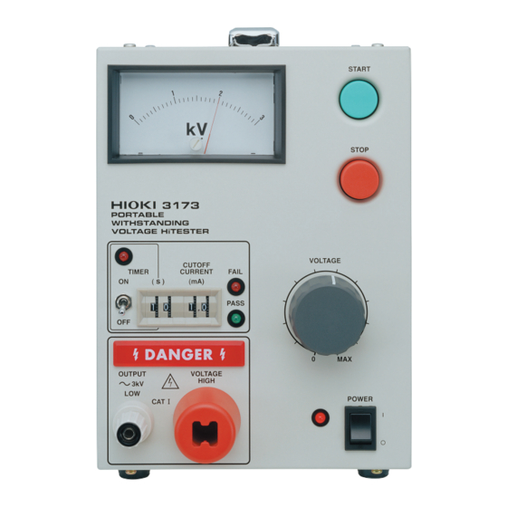
_____________________________________________________________________________________________ 1.2 Names and Functions of Parts 1.2.1 Front panel To avoid electric shock, never touch the output-voltage terminals (HIGH and LOW), high-voltage test leads or the device being tested while high WARNING voltage is being applied. Analog voltmeter START key Test timer LED STOP key Current threshold... - Page 13 One of the two LEDs will light, depending on the test result. START key Used to start a test. STOP key Normally used to terminate a test. Power switch Powers the 3173 on or off. The LED lights up when power is turned ON. ______________________________________________________________________________________________ 1.2 Names and Functions of Parts...
-
Page 14: Rear Panel
_____________________________________________________________________________________________ 1.2.2 Rear panel To avoid electric shock, never touch the output-voltage terminals (HIGH and LOW), high-voltage test leads or the device being tested while high WARNING voltage is being applied. External I/O terminal Power inlet Fuse holder Protective ground terminal Fuse holder Contains a power fuse. -
Page 15: 9615 H.v. Test Lead
_____________________________________________________________________________________________ 1.2.3 9615 H.V. TEST LEAD To avoid electric shock, do not touch the alligator clip while high voltage is being generated. The vinyl sheath on the alligator clip of the DANGER 9615 H.V.TEST LEAD does not have an insulation withstand voltage. High-voltage side (red) Low-voltage side (black) Alligator clip... -
Page 16: External Dimensions
_____________________________________________________________________________________________ 1.3 External Dimensions 200 2 mm 7.87 0.08" 149 2 mm 5.87 0.08" 215 2 mm 8.46 0.08" ______________________________________________________________________________________________ 1.3 External Dimensions... -
Page 17: Chapter 2 Testing Arrangements
_____________________________________________________________________________________________ Chapter 2 Testing Arrangements 2.1 Installation of the Unit Temperature: 0 to 40 (32 to 104 ) Humidity: 80% RH or less (no condensation) Do not place the tester upside down. Be sure to place the tester with its bottom side down. Avoid the following locations: ・Subject to direct sunlight. -
Page 18: Connecting The Protective Ground Terminal
_____________________________________________________________________________________________ 2.2 Connecting the Protective Ground Terminal To avoid electric shock, be sure to connect the protective ground terminal to a grounded conductor. WARNING To avoid electric shock, connect the protective ground terminal to a grounded conductor before making any other connections. . -
Page 19: Connecting The External I/O Terminal
_____________________________________________________________________________________________ 2.3 Connecting the External I/O Terminal Connect the external I/O terminal before turning on the power. If the external I/O terminal is installed or removed following startup, malfunction may result. . Press and hold the button on the terminal block using a flathead screwdriver. -
Page 20: Power Cord Connection
_____________________________________________________________________________________________ 2.4 Power Cord Connection Before turning the product on, make sure the source voltage matches that indicated on the product's power connector. Connection to an WARNING improper supply voltage may damage the product and present an electrical hazard. . Be sure that the power switch is turned to OFF. . -
Page 21: Connecting The 9615 H.v. Test Lead
Using the product under such conditions could result in electrocution. Replace the test leads specified by Hioki . . Remove the LOW terminal by turning it counterclockwise. LOW terminal . -
Page 22: Connection To The Measured Equipment
_____________________________________________________________________________________________ 2.6 Connection to the Measured Equipment Observe the following precautions to avoid electric shock. Turn off the power unit and tested object, make sure that there is no WARNING high voltage being applied to the output, confirm the following items, and connect the 9615 H.V. -
Page 23: Powering On And Off The 3173
_____________________________________________________________________________________________ 2.7 Powering On and Off the 3173 Before turning on the power, make sure that the voltage of the power supply being used matches the supply voltage indicated on the rear WARNING panel of the unit. If an attempt is made to use an improper supply voltage, there is danger of damage to this unit and of life-threatening risk to the operator. -
Page 24: Startup Inspection
_____________________________________________________________________________________________ 2.8 Startup Inspection To ensure safe testing, check the following before starting operation: (1) Breaking current . Calculate the resistance based on the output-voltage set for withstand voltage testing and the upper test value, and prepare a resistor corresponding to the calculation result. Note the power rating of the resistor. -
Page 25: Chapter 3 Withstand Voltage Testing Method
_____________________________________________________________________________________________ Chapter 3 Withstand Voltage Testing Method This chapter describes how to set withstand voltage test conditions and the proper testing procedure. Read Chapter 2, and make the necessary preparations for testing. Note that the output waveform may be distorted when conducting an AC NOTE withstand voltage test for a voltage-dependent device or object (e.g., ceramic capacitor). -
Page 26: Starting A Test
_____________________________________________________________________________________________ 3.1 Starting a Test The flowchart below explains how a test is carried out. Setting the test parameters 「READY 状態」 See Section 3.1.1 "Setting the Current Threshold Value (Upper Limit Value)" and Section 3.1.2 "Setting the Timer (Test Time)" Set the following before starting the test: ・Current threshold value (upper limit value) setting ・Timer (test time) setting... -
Page 27: Setting The Current Threshold Value (Upper Limit Value)
_____________________________________________________________________________________________ 3.1.1 Setting the Current Threshold Value (Upper Limit Value) . Make sure the analog voltmeter is at 0 kV and the lamp is OFF. DANGER . Turn the current threshold setting dial to set the threshold to the desired level. -
Page 28: Setting The Timer (Test Time)
_____________________________________________________________________________________________ 3.1.2 Setting the Timer (Test Time) . Make sure the analog voltmeter is at 0 kV and the lamp is OFF. DANGER . Turn the test timer setting dial to set the timer (test time). . Turn the test timer switch ON. The timer (test time) can be set from 1 to 99 s (setting resolution: 1 s). -
Page 29: Setting The Output-Voltage
_____________________________________________________________________________________________ 3.1.3 Setting the Output-voltage Before starting a test, make output-voltage settings using the output-voltage adjustment knob. Observe the following precautions to avoid electric shock. Make sure that no high voltage is being applied to the output, confirm DANGER the following items, and connect the H.V. TEST LEAD. (1) The analog voltmeter reads 0 kV. -
Page 30: Executing A Test
_____________________________________________________________________________________________ 3.1.4 Executing a Test Observe the following precautions to avoid electric shock. Make sure that no high voltage is being applied to the output, confirm DANGER the following items, and output-voltage. (1) The analog voltmeter reads 0 kV. (2) The lamp is OFF. -
Page 31: Pass Or Fail Determination
_____________________________________________________________________________________________ 3.2 PASS or FAIL Determination 3.2.1 "PASS" State Confirm the following items, before touching the output-voltage terminals (HIGH and LOW), H.V. TEST LEAD, or tested object. Even WARNING when a test has been terminated, there may still be voltage in the output-voltage terminals. -
Page 32: Fail" State
_____________________________________________________________________________________________ 3.2.2 "FAIL" State Confirm the following items, before touching the output-voltage terminals (HIGH and LOW), H.V. TEST LEAD, or tested object. Even WARNING when a test has been terminated, there may still be voltage in the output-voltage terminals. (1) The analog voltmeter reads 0 kV. (2) The lamp is OFF. -
Page 33: Chapter 4 External Interface
_____________________________________________________________________________________________ Chapter 4 External Interface 4.1 External I/O Terminal This tester has five external control signal terminals on its rear panel: PASS ――――――― and FAIL (relay contact output), TEST (open collector output without pull- ――――――――― ―――――――― up), START and STOP (input, 5 V pull-up). -
Page 34: Signal Line
_____________________________________________________________________________________________ 4.1.1 Signal Line Input Signals ――――――――― (1) START (Wired "OR" connection with key: Low active) START Measurement begins when this signal becomes low at the specified timing. (This is equivalent to pressing the START key.) This terminal is connected with START key input as a wired OR gate. - Page 35 _____________________________________________________________________________________________ Output Signals (1) PASS (Relay contact output) This signal is turned ON when the tester returns a PASS judgment. (2) FAIL (Relay contact output) This signal is turned ON when the tester returns a FAIL judgment. ―――――――― (3) TEST (Open collector output: Low active) Indicates that the tester is outputting a high voltage.
-
Page 36: Timing Chart Of External I/O Terminal
_____________________________________________________________________________________________ 4.1.2 Timing Chart of External I/O Terminal (1) Timing chart at time of start of testing ――――――――― The figure below shows a timing chart after a START signal is input and a test is begun. ――――――――― ―――――――― If the key ( START signal) and key ( STOP... - Page 37 _____________________________________________________________________________________________ (3) PASS Judgment Timing Chart The figure below shows a timing chart for when the set test time has elapsed and the test returns a PASS judgment. End of test time Operation Stop Test timer 5 ms or less 0.45 s approx.
-
Page 38: Example Of External I/O Terminal
560 Ω To the internal circuit ――――――――― input terminal START 56 kΩ 0.1 μF COM terminal START key Inside of 3173 ――――――――― input terminal START 560 Ω To the internal circuit ―――――――― input terminal STOP 200 kΩ 0.1 μF... - Page 39 START ―――――――― input terminal STOP START or STOP at SW ON Figure a Inside of 3173 COM terminal 10 mA Figure b For connection to the input signal, provide a circuit that protects the relay and NOTE switch from chattering to prevent malfunctioning.
-
Page 40: Example Of Output Signal Connection
To interlock with an external device by controlling a load (e.g., relay), connect as shown below. V_ext 30 V or less ――――――― signal TEST 20 mA or less Load Inside of 3173 Figure a V_ext 30 V or less ――――――― signal TEST 20 mA or less Load... - Page 41 To generate signal levels, connect the terminals as shown below. Note the output current. V_ext ――――――― signal TEST 30 V or less V_out 20 mA or less Inside of 3173 Maximum Minimum V_outH V_ext V_ext-1.5 V_outL ― The output signal status upon power-on may be undetermined. Care should be NOTE taken in the operation of equipment connected to the external I/O.
- Page 42 _____________________________________________________________________________________________ ______________________________________________________________________________________________ 4.2 Example of External I/O Terminal...
-
Page 43: Chapter 5 Specifications
_____________________________________________________________________________________________ Chapter 5 Specifications 5.1 Basic Specifications Voltage Generator Voltage 0 to 3.0 kV AC (Single range) Voltage testing Zero-toggle switch method Transformer 30 VA capacity Voltage adjustment Manually adjusted method Voltage Analog, 0 to 3 kV AC f.s., Accuracy: 5%f.s. - Page 44 _____________________________________________________________________________________________ Timer Section Setting range 1 to 99 s Operation ON : Test continues until the set time elapses. OFF : Test continues until STOP input or FAIL judgment. Setting resolution 1 s (1 to 99 s), (1% + 50 ms) of the set level and accuracy Interface EXT I/O Input Signals...
-
Page 45: General Specifications
3173: 100 V AC 3173-01: 120 V AC 3173-02: 220 V AC 3173-03: 230 V AC 3173-04: 240 V AC (Common to all voltages: 50 VA) Dimensions 149W X 200H X 215D mm (5.87"W X 7.87"H X 8.46"D) Approx. (excluding projections) -
Page 46: 9615 H.v. Test Lead Specifications
_____________________________________________________________________________________________ 5.3 9615 H.V. TEST LEAD Specifications Rated voltage HIGH : 5 kV AC / 5 kV DC LOW : 600 V AC / 600 V DC Rated current HIGH : 150 mA AC/ 150 mA DC LOW : 10 A AC / 10 A DC Dielectric strength HIGH : 6.25 kV AC, sensitivity current 5 mA, 1 minute LOW : 1.35 kV AC, sensitivity current 5 mA, 1 minute... -
Page 47: Chapter 6 Maintenance And Servise
Hioki representative. When reshipping the product, pack the product carefully so that it will not be damaged during shipment, and include a detailed written description of the problem. Hioki cannot be responsible for damage that occurs during shipment. Troubleshooting Symptom... -
Page 48: Cleaning
_____________________________________________________________________________________________ If any of the following should occur, stop using the unit, disconnect the power cord and 9615 H.V.TEST LEAD, and contact your dealer or HIOKI representative. ・If you are certain that the unit is damaged. ・If the measurement you wish to perform is inoperative. -
Page 49: Fuse Replacement
Fuse type: 250VT1AL ( 250VT0.5AL ( 3173, 3173-01), 3173-02, 3173-03, 3173-04) Turn the power OFF, and disconnect the power cord. Unlock the fastener on the fuse holder on the rear panel using a slotted screwdriver, and remove the fuse holder. - Page 50 _____________________________________________________________________________________________ ______________________________________________________________________________________________ 6.3 Fuse Replacement...
Need help?
Do you have a question about the 3173 and is the answer not in the manual?
Questions and answers