Table of Contents
Advertisement
Quick Links
Download this manual
See also:
Instruction Manual
Advertisement
Table of Contents

Related Manuals for Hioki 3554


Summary of Contents for Hioki 3554
- Page 1 OPERATIONS MANUAL HIOKI 3554 Industrial Batteries & Energy Storage...
-
Page 2: Table Of Contents
Contents Introduction ............................6 Verifying Package Contents ........................ 6 Safety Information ..........................7 Operating Precautions ........................9 Chapter 1 Overview ........................ 12 1.1 Measuring Battery Wear ......................12 1.2 Product Overview ........................13 1.3 Features ............................13 1.5 Names and Functions of Parts ....................14 1.5 Measurement Flowchart...................... - Page 3 3.7 Temperature Measurement ....................... 34 Chapter 4 Comparator Feature ....................36 4.1 Overview ............................. 36 4.2 Turning on the Comparator ......................36 4.3 Setting Comparator Permissible Values ..................37 4.4 Setting the Comparator Buzzer ....................41 4.5 Turning off the Comparator ......................42 Chapter 5 Memory Feature .....................
- Page 4 7.4.3 Preparing a New Table of Permissible Values ................60 7.4.4 Editing Files of Permissible Values ................... 62 7.4.5 Editing a Table of Permissible Values on the 3554 ..............63 7.4.6 Transferring Tables of Permissible Values ................64 7.4.7 Reading Data from the 3554’s Internal Memory ..............65 7.4.8 Deleting Data from the 3554’s Internal Memory ..............
- Page 5 10.6.1 Model 9460 Clip Type Lead with Temperature Sensor ............87 10.6.2 Model 9466 Remote Control Switch ..................87 10.6.3 Model 9467 Large Clip Type Lead ..................87 10.6.4 Model 9772 Pin Type Lead ..................... 88 10.7 Calibration Procedure ....................... 88 10.7.1 Resistometer Calibration .......................
-
Page 6: Introduction
Introduction Thank you for purchasing the HIOKI 3554 Battery HiTester. To obtain maximum performance from the instrument, please read this manual first, and keep it handy for future reference. Verifying Package Contents When you receive the instrument, inspect it carefully to ensure that no damage occurred during shipping. -
Page 7: Safety Information
Safety Information This instrument is designed to comply with IEC 61010 Safety Standards, and has been thoroughly tested for safety prior to shipment. However, mishandling during use could result in injury or death, as well as damage to the instrument. Be certain that you understand the instructions and precautions in the manual before use. - Page 8 f.s. (maximum display value or scale length) The maximum displayable value or scale length. This is usually the name of the currently selected range. rdg. (reading or displayed value) The value currently being measured and indicated on the measuring instrument. dgt.
-
Page 9: Operating Precautions
Operating Precautions Setting up the Instrument Operating temperature and humidity: 0 to 40°C (32 to 104°F), 80%RH or less (non-condensating) Accuracy guarantee for temperature and humidity: 23 ± 5°C (73 ± 9°F), 80%RH or less (non-condensating) Avoid the following locations that could cause an accident or damage to the instrument: Exposed to direct sunlight Exposed to high temperature Exposed to liquids... - Page 10 After use, turn OFF the power. Measurement Precautions Observe the following to avoid electric shock and short circuits. Do not measure voltages of 60V DC or higher. Do not measure grounded voltages of more than 70V DC. Do not measure alternating voltage. Be sure to connect the test leads properly.
- Page 11 Handling the CD Always hold the disc by the edges, so as not to make fingerprints on the disc or scratch the printing. Never touch the recorded side of the disc. Do not place the disc directly on anything hard. Do not wet the disc with volatile alcohol or water, as there is a possibility of the label printing disappearing.
-
Page 12: Chapter 1 Overview
Chapter 1 Overview 1.1 Measuring Battery Wear For determining battery wear, first measure internal resistance in a new or good battery. The graph below shows the relation between storage capacity and initial value of internal resistance in a lead-acid battery. ‘CS’, ‘HS’ and ‘MSE’ denote lead-acid battery types. Internal resistance of an MSE (sealed stationary lead-acid battery) can be read at approximately 1mΩ... -
Page 13: Product Overview
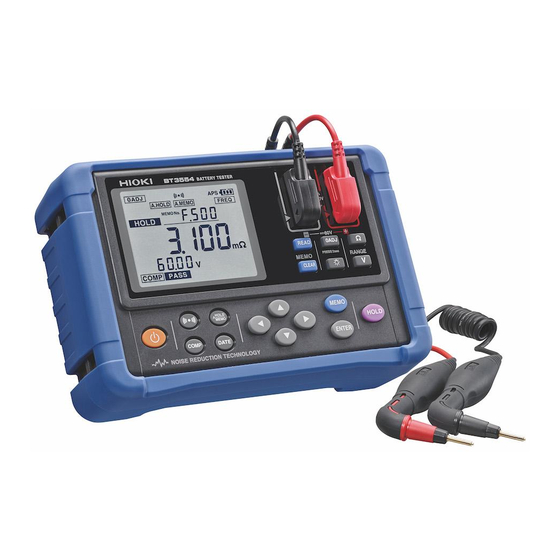
1.2 Product Overview The 3554 Battery HiTester is a measuring instrument for judging battery wear by measuring internal resistance, voltage, and terminal temperature of lead-acid, lithium-ion and other types of batteries. By connecting the instrument to a computer after measurement, using the included USB cable, measurement data can be loaded to the computer. -
Page 14: Names And Functions Of Parts
Large memory capacity Combining currently measured values (resistance, voltage, temperature and comparator measurement results) into a set, this instrument can store up to 4800 sets of data. It can be used to measure up to 12 sets of 400 cell cubicles. Auto-memory feature Enabling this function results in measurement data being stored to the instrument’s internal memory automatically, the instant it is held. - Page 15 Used for turning the comparator feature on or off and configuring thresholds and other values. Used for turning the auto-hold and auto-memory features on or off. Used for displaying the current date and time. Press this key for at least two seconds to set the clock.
- Page 16 Displayed when the zero-adjust feature is enabled. Displayed when the auto-hold feature is enabled. Displayed when the auto-memory feature is enabled. Displayed when the comparator button is turned on. Displayed when the auto-power-save feature is enabled. Indicates the remaining battery power. Displayed when the averaging feature is enabled.
-
Page 17: Measurement Flowchart
1.5 Measurement Flowchart The measurement workflow is described below: Measurement Preparations 1. Attaching the strap 2. Check the instrument’s remaining battery power 3. Connecting the test lead 4. Turning the power on 5. Setting clock 1300 734 253 sales@regalelectro.com.au www.regalelectro.com.au Industrial Batteries &... - Page 18 Setting Range 1. Setting the resistance range 2. Setting the voltage range Zero-Adjustment Implement the zero-adjust feature in accordance with the zero-adjust method for the test lead used. Starting Measurement 1. Connect the test lead to the subject of measurement. 2.
-
Page 19: External Dimensions
1.6 External Dimensions 1300 734 253 sales@regalelectro.com.au www.regalelectro.com.au Industrial Batteries & Energy Storage... -
Page 20: Chapter 2 Measurement Preparations
Chapter 2 Measurement Preparations 2.1 Attaching the Strap By attached the strap, the instrument can be used hung from the operator’s neck. Attach the strap as described below. Attach four ends of the strap securely to the instrument. If insecurely attached, the instrument may fall and be damaged or result in injury when carrying. -
Page 21: Connecting The Test Lead
1. Turn off the power to the instrument and remove the test lead. 2. Open the battery compartment cover on the rear of the instrument. 3. Insert 8 batteries, taking care to use the proper polarities. 4. Replace the battery compartment cover. 2.3 Connecting the Test Lead To avoid electric shock, be sure to connect the test leads properly. -
Page 22: Turning The Power On And Off
External Dimensions of the 9465-10 Pin Type Lead Connecting the Test Lead and Remote Control Switch The 9465-10 or the 9772 Pin Type Lead (optional) and the 9466 Remote Control Switch (optional) can be combined as shown below. Connect the switch to the probe of the lead, and join the two cables using the supplied spiral tube. 2.4 Turning the Power On and Off key to turn the power on and off. -
Page 23: Clock-Setting
indicator flashes when battery voltage (V) becomes low. Replace the new batteries soon. 2.5 Clock-Setting You can display the date and time by pressing key. Check the clock settings when using the instrument for the first time. 2.5.1 Turning Date and Time Display On and Off Press key to switch date and time display on and off. - Page 24 2. Use keys to change the date and time settings. keys to switch between settings. 3. Press key to save the date and time settings. If you exit the clock-setting screen without pressing key, your settings will not be saved. 1300 734 253 sales@regalelectro.com.au www.regalelectro.com.au...
-
Page 25: Chapter 3 Measurement
Chapter 3 Measurement TO ENSURE SAFE MEASUREMENT, BE SURE TO READ THIS SECTION PRIOR TO MEASURING. Observe the following to avoid electric shock and short circuits! Do not measure voltages of 60V DC or higher. Do not measure grounded voltages of more than 70V DC. Do not measure alternating current. -
Page 26: Pre-Operation Inspection
3.1 Pre-Operation Inspection Subject of Inspection Method of Checking Is the fuse worn out? Touch the test lead to the zero-adjust board. If the resistance display still shows a value of ‘- - . - -‘ the fuse Is the test lead disconnected? might be worn out or the test lead disconnected. -
Page 27: Zero-Adjustment
After approximately one second passes with no settings made, the settings displayed will be entered and the instrument will return to the measurement screen. Voltage Measurement Range Press key to display the current settings. Press the key repeatedly to select the desired range. After approximately one second passes with no settings made, the settings displayed will be entered and the instrument will return to the measurement screen. -
Page 28: Shorting Methods For Various Test Leads
3.3.1 Shorting Methods for Various Test Leads Model 9465-10 Pin Type Lead Short the test leads using the four terminal AC method, with the included zero-adjust board. As shown in the illustration below, select a hole suited to the distance between terminals, on the battery subject to measurement. -
Page 29: Implementing The Zero-Adjust Feature
Model 9772 Pin Type Lead 3.3.2 Implementing the Zero-Adjust Feature 1. Check to ensure that the test leads are connected properly. If a lead is connected to the subject of measurement, disconnect it. 2. Press key for at least two seconds. This will cause the instrument to wait for adjusted values. -
Page 30: Cancelling The Zero-Adjust Operation
4. Begin automatic obtaining of adjusted values. Keep the test leads shorted until the zero-adjust operation is complete. 5. When the zero-adjust operation is complete, the icon will be displayed and the instrument will return to the measurement state: 3.3.3 Cancelling the Zero-Adjust Operation Pressing the key for at least two seconds while the zero-adjust feature is active will cancel the zero-adjust operation:... -
Page 31: Holding The Display
3.4 Holding the Display 3.4.1 Holding Holding the measurement values displayed on screen. Press key. The icons will be displayed, and the measurement values will be held: Holding cannot be conducted when the following values are displayed: ‘- - - -‘ 3.4.2 Cancelling a Hold Press key again to cancel the hold. -
Page 32: Determining Battery-Wear Judgement Values
Be sure not to insert or remove the mini-plug while the test lead is connected to the battery subject to measurement. Connect the handy switch only after disconnecting the test lead from the battery. Do not insert the mini-plug of the 9466 Remote Control Switch into the TEMP.SENSOR terminal. -
Page 33: Battery Measurement
3.6 Battery Measurement For determining battery wear, first measure the internal resistance in a new or good battery, and then set values for judging battery wear. 1. Configure the range and conduct the zero-adjust operation. 2. Connect the test lead to the battery. 3. -
Page 34: Temperature Measurement
A measurement value display of ‘OF’ indicates that the resistance or voltage values displayed exceed the relevant measurement range. If the voltage input if ‘OF’, a busser will sound. A resistance value display of ‘- - - -‘ indicates that the test lead is open or measurement cannot be conducted due to an electrical current irregularity caused by a disconnected test lead or other reasons. - Page 35 Avoid subjecting the temperature probe tip to physical shock, and avoid sharp bends in the leads. These may damage the probe or break a wire. Changing the Unit of Temperature (°C - °F) 1. Press key to turn the power off. 2.
-
Page 36: Chapter 4 Comparator Feature
Chapter 4 Comparator Feature 4.1 Overview The comparator feature can be used to determine in which of the following ranges measurements fall, by comparing them with pre-set permissible values and battery measured values; pass, warning or fail. Up to 200 comparator conditions can be set. Under the initial configuration, when a measurement falls in the warning or fail range, a buzzer will sound. -
Page 37: Setting Comparator Permissible Values
4.3 Setting Comparator Permissible Values Set the comparator permissible values (resistance upper limit no.1, resistance upper limit no.2 and the voltage lower limit). Example Permissible values for a battery with initial values (i.e. resistance and voltage values when new or in good condition) of 0.4Ω... - Page 38 Setting Range 1. Press key to select resistance range. Press key to select voltage range. (The position of the decimal point will move.) 2. Press key to save the settings. Resistance upper limit no.1 is flashing, and icon is displayed. Setting Resistance Permissible Values 1.
- Page 39 Setting Voltage Lower Limit 1. Press keys to set the values of voltage lower limit. Press keys to select digits. 2. Press key to save the settings. This will return the display to the measurement screen, with the comparator feature on. At this point, configuration settings are saved.
- Page 40 Measure Value: FAIL Comparator Comparison Table Judgement is conducted using the display and the buzzer, as shown in the following table: Resistance Upper Resistance upper Limit Limit No.1 No.2 Resistance (Low) Resistance Resistance (High) (Medium) Voltage Voltage (High) PASS WARN FAIL Lower Limit Voltage (Low)
-
Page 41: Setting The Comparator Buzzer
When the resistance upper limit no.1 and no.2 are set at the same value, the boundary conditions will be as shown below: Resistance ≤ Resistance Resistance < Resistance upper limit upper limit PASS FAIL no.1 no.2 4.4 Setting the Comparator Buzzer When using the comparator feature, the buzzer can be set to sound in accordance with judgement results. -
Page 42: Turning Off The Comparator
When you press key, the current comparator buzzer settings will be displayed. Keep the button pressed to switch between settings. After approx. one second passes with no settings made, the settings displayed will be entered and the instrument will return to the measurement screen. 4.5 Turning off the Comparator Pressing key when the comparator feature is on will turn off the comparator feature. -
Page 43: Chapter 5 Memory Feature
Chapter 5 Memory Feature 5.1 Overview Up to 4800 sets of currently measured values (date and time, resistance, voltage, temperature, comparator permissible values, results of judgement) can be saved. After measurement, saved data can be displayed or transferred to a computer. The following table shows the structure of the internal memory: Memory Structure Unit (12 units) -
Page 44: Saving Using The Ext.hold/Memo Terminal
2. If you want to save the data under a different number than the memory no. displayed, use the keys to change the value. After approx. one second passes with no settings made, the settings displayed will be entered and the instrument will return to the measurement screen. -
Page 45: Turning Off The Memory Feature
3. When pressing the PRESS button on the 9466 Remote Control Switch, the measured values will be held. When pressing the button again, the data will be saved to the selected memory 4. The hold feature will be turned off. Be sure not to insert or remove the mini-plug while the test lead is connected to the battery subject to measurement. -
Page 46: Deleting Saved Data
Press key to check the date and time of saving (which will be displayed while the key is de-pressed). The comparator results for the data being read will also be displayed. Numbers to which no data is saved cannot be selected. If no data has been saved, ‘- - - -‘... -
Page 47: Deleting An Entire Unit (400 Sets)
5.5.2 Deleting an Entire Unit (400 Sets) 1. Press key. This will display the reading screen. 2. Press keys to select the memory no. Press keys to select digits. 3. Press key two times. If there is no activity for approx. three seconds, the reading screen will be displayed. -
Page 48: Chapter 6 Other Features
Chapter 6 Other Features 6.1 Averaging Feature When measured values are unstable, they can be stabilised using averaging. The number of times averaging is conducted can be selected from four, eight, or sixteen times. When using this averaging feature, icon is displayed on the screen. This feature is turned off under initial settings and after resetting the system. -
Page 49: Auto-Memory Feature
Releasing the Hold Release the hold by pressing key or the PRESS button on the 9466 Remote Control Switch. When ‘- - - -‘ is displayed, the auto-hold feature cannot be used. The auto-hold function can be used when ‘OF’ is displayed on-screen. When using the auto-memory feature together with this feature, measured values can be saved automatically after holding them. -
Page 50: Auto-Power-Save Feature (Aps)
6.4 Auto-Power-Save Feature (APS) The auto-power-save feature can be used to control the instrument’s power consumption. When any of the following conditions has continued for approx. ten seconds with no keys pressed, power to the instrument will be turned off automatically. When the resistance value displayed is ‘- - - -‘... - Page 51 Saved measurement data (4800 data sets) Comparator permissible values (200 sets) 1. Press key to turn the power off. 2. While holding key down, press key. This will display the system reset screen. 3. Using keys, select ‘YES’. Select ‘no’ to cancel the system rest. 4.
-
Page 52: Battery Level Indicator
6.6 Battery Level Indicator The battery level indicator is displayed in the upper right-hand area of the screen. Battery Level Indicator Battery Status Battery condition when new alkaline batteries have been inserted. Battery conditions after approx. four hours of use. Battery condition after approx. -
Page 53: Chapter 7 Connecting With A Computer
The following software must be installed in order to enable communication between the instrument and a computer. Each of these are included in the CD accompanying the instrument. Communication driver Application software for 3554 7.1.1 Recommended Operating Environment Pentium III 500 MHz or more Compatible OS Windows 98SE, Me, 2000, XP Internet explorer 5.1 or later... -
Page 54: Composition Of Cd
Select ‘Small Font’ for use with the OS. Using ‘Large Font’ may cause irregularities in screen indications. 7.2 Installing the Software Before connecting the instrument to a computer, be sure to install Application Software for 3554. 7.2.1 Installation 1. Start up the computer 2. - Page 55 6. Enter your username and company name, and then click [Next]. 7. Click [Next]. Click [Browse] to change the directory to which the application will be installed. 1300 734 253 sales@regalelectro.com.au www.regalelectro.com.au Industrial Batteries & Energy Storage...
- Page 56 8. Click [Install]. Windows will begin installing. 9. When the installShield Wizard Complete appears, click the [Finish button. 10. After the installation is complete, complete the installation process by ejecting the CD from the CD-ROM drive. 1300 734 253 sales@regalelectro.com.au www.regalelectro.com.au Industrial Batteries &...
-
Page 57: Uninstalling (Removing) The Application
7.2.2 Uninstalling (Removing) the Application If Application Software for 3554 is active, be sure to close the application before uninstalling it. 1. Select the [Add or Remove Programs] in the Control Panel, under the Start menu. 2. Select [Application Software for 3554], and then click [Remove]. -
Page 58: Using The Software
If the remaining battery power is low, replace the batteries with new ones. 2. Connect the instrument to a computer using the included USB cable. Only one 3554 instrument may be connected to a computer at one time. 1300 734 253 sales@regalelectro.com.au... -
Page 59: Starting The Software
When connected to a computer, using the USB cable, the instrument will shift to PC mode and cease measurement operations. Power to the internal measurement circuitry will be turned off, and the instrument will shift to low power mode. 1. The APS feature is disabled while the instrument is in PC mode. 7.4.2 Starting the Software 1. -
Page 60: Preparing A New Table Of Permissible Values
The current data and time values of the computer’s clock will be displayed by default. If these are correct, simply click [Set] without changing them. The clock settings will be finalised and transmitted to the 3554 instrument. If you leave the clock setting screen by clicking [Back] without clicking [Set], the clock settings will not be saved. - Page 61 3. Click [New File]. [Edit Comparator Table] will appear. 4. Entering configurations for each table. (1) Enter the table no. This number can be selected by clicking [Previous table No.] or [Next table No.], or by clicking on the table. (2) Enter the name to be assigned to the table no.
-
Page 62: Editing Files Of Permissible Values
(4) Enter resistance upper limit no.1 (R-Lim 1), resistance upper limit no.2 (R-Lim 2 ), and the voltage lower limit (V-Lim). Enter resistance input values in units of mΩ. (5) Finalise the settings. Configure all tables by repeating steps (1) – (5) above. 5. -
Page 63: Editing A Table Of Permissible Values On The 3554
Editing the saved file using another application could make it unreadable by this application. 7.4.5 Editing a Table of Permissible Values on the 3554 1. Click [SET COMP/Clock] on the initialisation screen. 2. Click [COMP Table]. 3. Click [Edit 3554 data]. -
Page 64: Transferring Tables Of Permissible Values
5. After receipt of the table of permissible values is complete, click [OK]. 6. Editing configurations for each table. Refer to Section 7.4.3 Preparing a New Table of Permissible Values. Transfer takes approx. three seconds. 7.4.6 Transferring Tables of Permissible Values Transferring tables of permissible values will over-write all tables of permissible values stored on the instrument. -
Page 65: Reading Data From The 3554'S Internal Memory
The transfer time given is an approximation. The actual time needed may vary depending on the processing speed of the computer used. 7.4.7 Reading Data from the 3554’s Internal Memory The application can be used to read measurement data saved to the instrument’s internal memory. - Page 66 4. Select the directory to which to save the read data, enter a filename and then click [OK’. Data transfer will begin. Transfer of a single unit (400 units of data) takes approx. eight seconds. Transfer of all units (4800 units of data) takes approx. 90 seconds. The transfer times given are approximations.
-
Page 67: Deleting Data From The 3554'S Internal Memory
7.4.8 Deleting Data from the 3554’s Internal Memory The application can be used to read measurement data saved to the instrument’s internal memory. 1. Click [Read/Delete Data] on the initialisation screen. 2. Click [Delete Data]. 3. Click all numbers of the unit to delete. -
Page 68: Closing The Application
7.4.9 Closing the Application 1. Click [Exit] on the initialisation screen. 1300 734 253 sales@regalelectro.com.au www.regalelectro.com.au Industrial Batteries & Energy Storage... -
Page 69: Chapter 8 Specifications
Chapter 8 Specifications 8.1 General Specifications Measurement Modes Measurement of battery internal resistance Measurement of battery terminal voltage (DC V only) Temperature measurement Measurement Range (After 0 adjustment) Resistance 0.000mΩ to 3.100Ω (Four-range structure) Voltage 0.000V to ± 60.00V (Two-range structure) Temperature -10.0°C to 60.0°C / 14°F to 140°F (single range) Measurement Method... - Page 70 Averaging Feature Details of Operation Calculating a moving average of displayed resistance values Initial Status Configuration Method Change number of times averaging is conducted by pressing the AVG OFF (once) 4 times 8 times 16 times OFF … Zero-Adjustment Details of Operation Measured values upon implementation (upon obtaining adjusted values) are set at zero Initial Status...
- Page 71 Memory Feature Details of Operation While the measured values are being held, press the MEMO key to save them to the instrument’s internal memory. When the auto-memory feature is on, measured values will be saved to the instrument’s internal memory when held. Saved data can be deleted.
- Page 72 This feature is cancelled during data communication using the PC application. Comparator Buzzer Details of Operation ON (Sounds when result is PASS) ON (Sounds when result is FAIL/WARNING) Initial Status ON (Sounds when result is FAIL/WARNING) Battery Level Indicator Details of Operation Remaining battery power shown as zero at 8.0V (±...
- Page 73 Operated Using Formed rubber keys (18) Display LCD (monochrome, 159 segments) Guaranteed Accuracy For one year Period Operating 0°C to 40°C (32°F to 104°F) Temperature and 80%RH or less (non-condensating) Humidity Storage Temperature -10°C to 50°C (14°F to 122°F) and Humidity 80%RH or less (non-condensating) Operating Environment Indoors, altitude up to 2000m (6562ft) Power Supply...
- Page 74 Accessories Model 9465-10 Pin Type Lead USB Cable Application Software CD Strap Instruction Manual Carrying Case Zero-Adjustment Board LR6 Alkaline Batteries Fuse (216.315, Littelfuse, INC) (F315mAH/250V) Options Model 9460 Clip Type Lead with Temperature Sensor Model 9466 Remote Control Switch Model 9467 Large Clip Type Lead Model 9465-90 Tip Pin (For replacing the point of 9465-10) Model 9772-90 Tip Pin (For replacing the point of 9772)
-
Page 75: Accuracy
8.2 Accuracy Accuracy Guarantee for 23°C ± 5°C (73°F ± 9°F) Temperature and 80%RH or less (non-condensating) Humidity Guaranteed Accuracy Warming up: not required Conditions Zero-Adjustment: Implemented Temperature Calculated using temperature coefficient Coefficient (T – 23); T: Temperature used (°C) 18 to 28°C: no temperature coefficient Resistance Measurement Temperature Coefficient:... -
Page 76: Communications
Temperature Measurement Range Maximum Resolution Accuracy Displayed Value -10 to 60°C 60.0°C 0.1°C ± 1.0°C (14 to 140°F) (140.0°F) (0.1°F) (±1.8°C) Individual reliability under simulated input: ± 0.5°C (± 0.9°F) 8.3 Communications USB Interface Hardware Uses RS-232C/USB converter Operating Method When connecting the instrument to a computer via the USB cable, the instrument shifts to PC mode. -
Page 77: Chapter 9 Maintenance And Service
When sending the instrument for repair, remove the batteries and pack carefully to prevent damage in transit. Include cushioning material so the instrument cannot move within the package. Be sure to include details of the problem. Hioki and Regal Electro cannot be responsible for damage that occurs during shipment. -
Page 78: Error Display
If not, select an appropriate range using the range key. The Ω or V keys have no effect Is the comparator feature in effect? These keys cannot be operated when the comparator feature is in effect. The MEMO keys have no Has the data been held? effect If not, use the HOLD key to hold the data. -
Page 79: Frequently Asked Questions
The messages ‘- - - -‘ and ‘OF’ displayed on screen are not indicators of errors. ‘- - - -‘ is displayed when input terminals have been opened. ‘OF’ is displayed when the input values exceed the set range. Reset the range correctly. -
Page 80: Replacing The Fuse
9.4 Replacing the Fuse When the instrument’s fuse has burned out, replace it as described below. To avoid electric shock when replacing the fuse, first disconnect the test leads from the battery to be measured. After replacing the fuse, replace the fuse cover and screws before using the instrument. -
Page 81: Cleaning
4. Pull off the connector and remove the pin. 5. Fasten a new pin. Press the tip of the pin against a hard board so that the pin won’t spring out, and push the connector onto the pin. 6. Assemble the pin type lead in the reverse order of disassembling. Do not pull or twist the cable. - Page 82 1. Turn off the power to the instrument and remove the test leads. 2. Using a Phillips screwdriver, remove the four screws from the battery cover on the rear side of the instrument. 3. Remove the cable protruding from the battery holder. 4.
-
Page 83: Chapter 10 Appendix
Chapter 10 Appendix 10.1 Effects of Extending the Measurement Lead and Induced Voltage The test lead extension is normally performed by Hioki. If you want extension performed, contact Regal Electro. Users should not extend the measurement leads. Reducing Induced Voltage Since the instrument measures a minute resistance with AC power, it is affected by induced voltage. -
Page 84: Ac Four-Terminal Method
10.3 AC Four-Terminal Method The instrument uses the AC four-terminal method, so that resistance measurement can be carried out with the resistance of the leads and the contact resistance between the leads and the object to be measured cancelled out. The following figure shows the principle of the AC four-terminal measurement method. - Page 85 Use of Hioki’s 9453 four-terminal lead or a similar lead to detect voltage on the inner side of the sources of current is desirable to avoid these effects. In other words, if measurement is conducted within the width (W) or thickness (t) of the subject of measurement, current distribution is likely to be stable.
-
Page 86: Synchronous Detection System
Since when judging battery wear it is important to ascertain changes arising from the passage of time, use the same measurement lead for each measurement. 10.5 Synchronous Detection System The figure below shows an equivalent circuit for a battery. If the measured object exhibits other electrical characteristics in addition to resistance, as shown in the below image, we can use the synchronous detection system to obtain the effective resistance of the object. -
Page 87: Test Lead Options
10.6 Test Lead Options 10.6.1 Model 9460 Clip Type Lead with Temperature Sensor Resistance, voltage and temperature can be measured simultaneously. 10.6.2 Model 9466 Remote Control Switch By attaching this switch to the test lead, values can be held during measurement. 10.6.3 Model 9467 Large Clip Type Lead These can be clipped to samples in relatively thick bar form. -
Page 88: Model 9772 Pin Type Lead
10.6.4 Model 9772 Pin Type Lead This lead’s pins are arranged parallel to each other. It is a strong, wear-resistant lead. 10.7 Calibration Procedure To prevent damage to the instrument, do not input voltage between the positive SOURCE and SENSE terminals or between the negative SOURCE and SENSE terminals. Also, do not conduct measurement when the instrument is turned off. - Page 89 1300 734 253 sales@regalelectro.com.au www.regalelectro.com.au Industrial Batteries & Energy Storage...
Need help?
Do you have a question about the 3554 and is the answer not in the manual?
Questions and answers