Table of Contents
Advertisement
SHENZHEN VDWALL CO., LTD
en.vdwall.cn
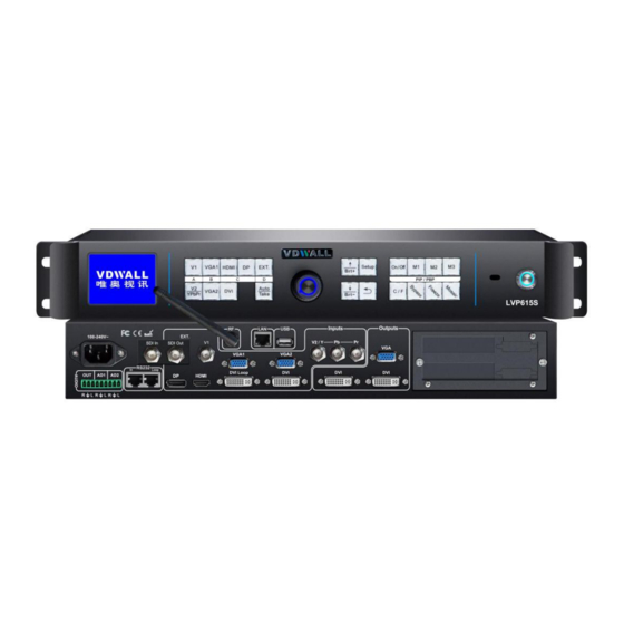
LVP615S
LED HD Video Processor
User Manual V1.2
Tel:
+86-755-2675 0210 / 2650 1506 / 2663 6668
Fax: +86-755-2675 0185
Add: Room 1001, 10th Floor, Tower 4, Fangda-city, Longzhu 4th Road, Nanshan District, 518073 Shenzhen, China
Web: en.vdwall.cn; www.videowall.cn
Advertisement
Table of Contents

Related Manuals for Vdwall LVP615S


Summary of Contents for Vdwall LVP615S
- Page 1 SHENZHEN VDWALL CO., LTD en.vdwall.cn LVP615S LED HD Video Processor User Manual V1.2 Tel: +86-755-2675 0210 / 2650 1506 / 2663 6668 Fax: +86-755-2675 0185 Add: Room 1001, 10th Floor, Tower 4, Fangda-city, Longzhu 4th Road, Nanshan District, 518073 Shenzhen, China...
-
Page 2: Table Of Contents
LVP615S series user manual Content Content Chapter 1: Safety precautions............................. 3 Chapter 2:Item List................................4 Chapter 3:Hardware connection............................5 3.1 Rear view................................5 3.2 Ports description..............................5 3.3 Hardware connection diagram........................7 3.4 Specifications..............................7 3.5 Product dimensions............................10 Chapter 4: Front panel and remote control instructions....................11 4.1 Front panel buttons and remote control schematic.................11... -
Page 3: Chapter 1: Safety Precautions
LVP615S series user manual Chapter 1: Safety precautions Chapter 1: Safety precautions !Danger There is high voltage in the processor, to prevent any unexpected hazard, unless you are maintenance, please do not open the cover of the device. !Warning This device shall not encounter water sprinkle or splash, please do not place anything containing water on this device. -
Page 4: Chapter 2:Item List
LVP615S series user manual Chapter 2: Item list Chapter 2:Item List Please unpack the product carefully, then check whether all the following things are included in the package. If anything is found missing, please contact the dealer. Standard accessories The accessories supplied with this LED Video Processor may differ from the figures contained in the User’s Manual, but they are applicable for the regions where you live.(LED sending... -
Page 5: Chapter 3:Hardware Connection
Chapter 3: Hardware connection Chapter 3:Hardware connection 3.1 Rear view 3.2 Ports description 3.2.1 Video signal inputs ( INPUT ) LVP615S supports 8 video signals input as follows: Port Description 1xComposite Video (PAL/ NTSC) V2 / YPbPr 1xComposite video (PAL/ NTSC) or analog component video input... - Page 6 Chapter 3: Hardware connection 3.2.2 Audio input signals(AUDIO) LVP615S supports 5-channel stereo audio inputs switching. Of which, 3 channels are DP and HDMI input. The other 2 channels are AD1, AD2 external audio input. AD1 and AD2 can be mapped to any one of signal inputs, and will be switched synchronous to the selection of video input signals.
-
Page 7: Hardware Connection Diagram
LVP615S series user manual Chapter 3: Hardware connection 3.3 Hardware connection diagram 3.4 Specifications Inputs 2×Video 1×YPbPr 2×VGA(RGBHV) Nums / Type 1×DVI(VESA /CEA-861) 1×HDMI(VESA /CEA-861) 1×DP(VESA) 1xEXT( SDI ) Video system PAL/NTSC Composite Video 1V(p_p)/ 75Ω Amplitude Impedance VGA format PC(VESA standard)... - Page 8 LVP615S series user manual Chapter 3: Hardware connection Amplitude R、G、B = 0.7 V(p_p)/ 75Ω Impedance YPbPr format SD/HD(CEA -861) ≤1920x1080p_60Hz Y=1V(p_p)/ 75Ω YPbPr Amplitude Pb= 0.35V(p_p)/ 75Ω Impedance Pr= 0.35V(p_p)/ 75Ω PC(VESA standard) ≤2304×1152_60Hz DVI format Width≤3840 , Custom output format Height≤1920...
- Page 9 LVP615S series user manual Chapter 3: Hardware connection 1536×1536_60Hz Custom output format ( maximum horizontal pixel:3840 , maximum vertical height:1920) VGA OUT:15Pin D-sub( female) Output connectors DVI OUT1:24+5 DVI_I DVI OUT2:24+1 DVI_D Others Control RS232/USB/LAN/Wi-Fi / Remote control Input voltage...
-
Page 10: Product Dimensions
LVP615S series user manual Chapter 3: Hardware connection 3.5 Product dimensions RS232 cable order:... -
Page 11: Chapter 4: Front Panel And Remote Control Instructions
Chapter 4: Front panel and remote control instructions Chapter 4: Front panel and remote control instructions LVP615S supports front panel button, remote control, RS232 and LAN control. Same printing on remote control buttons and front panel buttons,same button functions. The instructions are as below. - Page 12 LVP615S series user manual Chapter 4: Front panel and remote control instructions 4.1.1 Input signal selection buttons ) :select the input signal. ( , 4.1.2 Setup buttons( ), Set the output image parameters. , 4.1.3 VGA auto adjustment button ( )automatically adjust the VGA input signal.
-
Page 13: Remote Control Operation Instructions
4.2.1 Open the battery compartment on the back of the remote control, make sure the battery effective contact 4.2.2 Please aim remote control to the sensor area of LVP615S, if there is obstacle between them, LVP615S may not receive command. -
Page 14: Chapter 5: Basic User Instructions
Chapter 5: Basic user instructions After LVP615S boot, it enters the operation status of last shut-down including signal switching status, PIP/POP (or Text overlay) status and mosaic status. Among them, PIP/PBP( or text overlay) status and mosaic status can only realize relative functions and cannot do other operation. - Page 15 LVP615S series user manual Chapter 5: Basic user instructions 5.1.1 One key switch LCD screen display as below: Input: HDMI In Status: 1080p_60Hz -------------------------------------- Output Size: 1920x1080 Output Start: (0,0) -------------------------------------- Switch Mode: One Key SW. Switch Time: 1.5 Sec After select input signal, The first line on the LCD display the current input signal.
- Page 16 In the signal switching status, press C/F button continually can change the current seamless switching transition time. LVP615S can achieve seamless switching between any two different input groups of four input groups. Switching effect includes seamless switching (0s), Fade in/ Fade out (o.5s 1s 1.5s) and blend switching.
-
Page 17: Pip / Pbp Operation
5.2 PIP / PBP operation LVP615S allows to insert PIP window on the current display signal. That is dual image display function(PIP/PBP)。 PIP signal can be any input signal from other input groups or current input signal itself. -
Page 18: Mosaic Operation
Multiple units LVP615S cascading can drive huge resolution LED screen. Only when the current input is DVI, press Mosaic button and the indicator is on. LVP615S enters to Mosaic operation. Press the button again and the indicator is off, LVP615S exits Mosaic. -
Page 19: Other Basic User Operation
5.4.2 VGA input auto adjustment (Auto) When LVP615S is in one key switch status and current valid input signal is VGA, press Auto button to adjust VGA input signal sampling parameters. Then the VGA output image can be clear and full. - Page 20 Part display is invalid. 5.4.4 Text overlay LVP615S allows for overlapping text, logo or flash on the current image. The operation is as below. When the current input display properly, enter setup menu“3.Text overlay”,set ”3.1text overlay” on, then select text source.Text can be produced by PowerPoint and other office software.
- Page 21 LVP615S series user manual Chapter 5: Basic user instructions System info -------------------------------------- model: LVP615S version: V0.0.8/V0.0.8 IP: 192.168.1.8 Mask: 255.255.255.0 Gate: 192.168.1.1 MAC: 76-64-77-00-00-00 Device ID:...
-
Page 22: Chapter 6: Setup Menu Instructions
LVP615S series user manual Chapter 6: Setup menu instructions Chapter 6: Setup menu instructions Setup menu is to set the entire processor. There are 9 section including output image、 input image、 text overlay、 image quality、audio、communication、language、advance、PIP/PBP、mosaic. setup -------------------------------------- 1. Out Image >>... - Page 23 Chapter 6: Setup menu instructions 6.1.1 Set output format LVP615S can output image from the VGA OUT and 2 DVI OUT. There are 16 fixed output format and custom output format.(refer to page 9specifications). Users can select fixed output format not less that the LED screen resolution or select custom output format which can realize pixel to pixel display in concert with 2.1 .1 custom DVI EDID.
- Page 24 LVP615S out image area Out vert height LED screen LVP615S output resolution = 1920×1080 1920 As shown in the above picture: the size and location of output image of LVP615S can be defined in 4 parameters: Item NO. Item name Out_hori_width...
-
Page 25: Input Video Signal Setting
Chapter 6: Setup menu instructions 6.1.3 Test pattern LVP615S can generate 36test patterns for LED screen testing. If this item value is “off”, turn off Test pattern. Select other number and confirm.Then one corresponding test pattern of 36 pcs will be selected. - Page 26 LVP615S supports custom DVI EDID. In concert with “custom output format” , LVP615S can realize DVI input image and output image pixel to pixel display. LVP615S supports 16 fixed DVI EDID and custom EDID. Normally the parameters setting should be consistent with“custom output...
- Page 27 V1 signal is lost, processor will switch to V2 automatically. 6.2.3 V2 or YPbPr selection V2 and YPbPr of LVP615S share the same port and button. Need configure. Default input is V2. If need YPbPr input, then need set this port to YPbPr. Operation steps:...
-
Page 28: Text Overlay Setting
3.1 text overlay and switch it off. 6.3.2 Text overlay parameters setting 3.1Text mode:LVP615S can custom text mode < threshold or > threshold. < threshold means text signal image which is less than the current threshold value will overlay on the current signal. The bigger part will be automatically filtered out. -
Page 29: Image Quality Setting
LVP615S series user manual Chapter 6: Setup menu instructions Text mode <threshold Threshold R Threshold G Threshold B Main picture text text overlay 6.4 Color& Brightness,etc. 4.Color&Brightness Default -------------------------------------- 4.1 Input color V1=50 V2=50 HDMI=50 DVI=50 DP=50 EXT=50 V1=50 All=50 4.2 Sharpness... - Page 30 LVP615S series user manual Chapter 6: Setup menu instructions 4.Color&Brightness Default -------------------------------------- 4.3 Brightness LVP615S supports custom color,sharpness and brightness setting. List as follow: Item name Definition 4.1 color Adjustment range:0~100, default 50 4.2 sharpness Normal or sharp,default : normal.
-
Page 31: Audio Setting
5.1 AD1 Config 5.2 AD2 Config LVP615S supports 4 channels of stereo audio input signals. Three of them are HDMI and DP audio. The other two AD1 and AD2 are external input. Audio input signals for AD1 and AD 2 can be configured to match the video input signals correspondingly and switching between AD1 and AD2 is synchronous to that between the video inputs. -
Page 32: Communication
OK to save. The LCD screen will give tips to restart the system and do according to the prompt. 6.7 Language setting LVP615S supports Chinese and English language.Rotate knob to select one and press OK to save. 7. Language -------------------------------------- 7.1 语言... -
Page 33: Advance Setting
But this will also bring information loss of images, especially dark images like night scenes. LVP615S can adjust“ 8.2 Bias ” parameters to adjust. The value range is :0— 100. In the case dark image information lost, adding this value will bring back the lost information and fully display the image on LED display. - Page 34 LVP615S series user manual Chapter 6: Setup menu instructions 6.8.3 EXT. Input Model The option is used to configure extended module after replacing it, to make sure the module can work normally. Operation is as below: Entering “8.3 EXT. Input Model” option, rotate knob to select relative option, press OK button to save.
- Page 35 6.8.7 Wi-fi reset The menu item is used for resetting LVP615S’s Wi-fi module parameter. Operations as below: Enter “8.7 Wi-fi Reset”, press “OK” button, there is one information on LCD screen to remind you data will reset. Press OK button to apply.
-
Page 36: Pip / Pbp Setting
When LVP615S’s PIP/PBP status is open (the indicator light on “On/Off” button is lit up), press Setup button, LVP615S enters “D. PIP/PBP” menu. Then press mode button (M1, M2 or M3) to select a mode to save parameters, press ↓ to select parameter option needed to adjust. For example “D.1 Main Width”, rotate knob to change parameter, press OK button to save. -
Page 37: Mosaic Setting
LVP615S provides 2 positions for two built-in transmission cards. If the actual definition of LED display exceeds the maximum output definition of LVP615S, you may divide the whole LED screen into pieces of smaller LED screens, then put them together in Mosaic manner by connecting multiple sets of LVP615S in parallel to integrate the smaller pieces of LED screens into a large LED display. - Page 38 LVP615S supports multiple units cascading splicing. By this way, smaller pieces of LED screens can be integrated into a large display. For example, if the output definition of LVP615S is set as 1920×1080, and we put 2 sets of LVP605 together horizontally in parallel, it will be able to connect any LED display of up to 3840×1080 pixels...
- Page 39 Chapter 6: Setup menu instructions Operation is as below: When the input signal of LVP615S is DVI format and the splicing mode is open (Mosaic indicator lit up), press Setup, LVP615S enters splicing menu. Press ↓button to select setup option needed to adjust, rotate knob to change parameter, press OK button to save.
- Page 40 As above diagram shows, all input signals are connected to and switched by #0 LVP615S. The 2 same DVI outputs of #0 LVP615S are connect to #1 LVP615S and #2 LVP615S. Then DVI loop to #3 and #4. After that, the output signal of #0 LVP615S is cropped and scale up in #1 LVP615S, #2 LVP615S, #3 LVP615S and #4 LVP615S.
- Page 41 LVP615S series user manual Chapter 6: Setup menu instructions In order to ensure all output images are synchronous to each other, please note the following settings: 1. The input signals can be only DVI signals, and if the processor is in mosaic mode, it will be unable to switch input signals;...
-
Page 42: Chapter 7:Remote Control Instructions
LVP615S opens RS232 control protocol supporting PC, Android or IOS intelligent remote control terminal. Here we instruct the hardware connection and software operation as below. 7.1 Hardware communication LVP615S remote control ports include RS232, USB, Wired network and Wi-fi control. As below we illustrate hardware communication connection and setup respectively. LVP615S Remote communication ports 1 :RS232... - Page 43 (refer user manual page 38 “6. Communication ”), LVP615S has been a work station in the local area network. So another terminal device in the local area network can control the LVP615S through software. As the picture below, through software, anyone of terminal (work station) in the local area network can control the LVP615S in the local area network by remote method.
- Page 44 7.1.3.1 Wi-Fi connection Using laptop with wireless network, open network and share center, search and connect the wireless network named LVP615S, the default WIFI password is 88888888 Configuring network be automatically obtain IP address and DNS server address, show as the...
- Page 45 Chapter 7: Remote control instructions 7.1.3.2 Wireless Module Configuration 1) Running wireless scan configuration software “LVP615S Wi-Fi Config Tool.exe”, the application software is as below. Click “Scan” to search LVP615S in the local area network, after searching module the information display as below.
- Page 46 LVP615S series user manual Chapter 7: Remote control instructions In scan list click relative Wi-Fi module, when appear dialog box, type in user name (default name is admin) and password (default password is admin), software will remind “module identify successfully” and “obtain configuration parameter successfully”, meanwhile software interface will display relative information.
- Page 47 Mainly used to reset module, or control WIFI in the status of no local area network. (Recommended) Make the LVP615S as a work station, configure and join a wireless network. It can be realized by typing in router name and password.
- Page 48 LVP615S series user manual Chapter 7: Remote control instructions Click search key to find the around wireless network. STA setting Notice: Better use manual method instead of automatic method to avoid disconnection due to IP address changes.
- Page 49 LVP615S series user manual Chapter 7: Remote control instructions c. Serial Port Parameter Setting This step is for setting basic parameters of serial port, after modifying configuration, click “save” button to save change. As the picture below shows, the boardrate should be 9600.
-
Page 50: Pc Control Software Instructions
See the picture below: 7.2 PC control software instructions LVP615S’s control software used to control LED HD video processor LVP615S. Through the software, we can realize: Selecting input signal switch by seamless switching or fade in fade out mode ... - Page 51 Chapter 7: Remote control instructions 7.2.1 Control method As illustrated above, the PC remote control of LVP615S can realize connection by RS232, USB, LAN or Wi-Fi. After connecting and needed configuration, we can run the control software: “LVP615S Control Software.exe”...
- Page 52 COM port number can be checked in PC’s “device manager”, show as the picture below: The device ID number you select must be as same as the LVP615S’s which you need to controlled. If select network connection, firstly must set the network connected being correct, the relative setup about wired network prefer 6.
- Page 53 LVP615S series user manual Chapter 7: Remote control instructions Click “connect” button, the software shows. After the device connecting successfully, every function button in software inter face has been activated. Information area on main interface displays reminder connecting successfully. Setting timer automatically start: to select whether the processor automatically connect serial port and automatically open the timing control in next starting up.
- Page 54 LVP615S series user manual Chapter 7: Remote control instructions The buttons of the signal area respectively represent the corresponding keys and status indicators in the panel of the processor. After the device is successfully connected, the software will read the input signal source you currently selected and the blue indicator above it will turn on.
- Page 55 If operation is unsuccessfully, the information area will display the reason of failing. 7.2.2.6 Timing control setup The Timer of the Control Software can switch the input signal source of LVP615S as per the preset timer plan. The system provides four cycle timer modes, i.e.: Day, Week, Month, Once.
- Page 56 LVP615S series user manual Chapter 7: Remote control instructions Setting timing parameter In user interface click Program, appear setup interface of timer, show as the picture below: Show as the picture above, there are two types of plan: (1)Cycle Plan (2)Once plan...
- Page 57 LVP615S series user manual Chapter 7: Remote control instructions Select the plan already added, then you can modify or delete it. 7.2.2.7 Output date setup In user main interface click Setup, appearing the setup interface of output parameter, in the interface user can set output parameters of processor.
- Page 58 LVP615S series user manual Chapter 7: Remote control instructions The setting parameter in interface has zury background indicates the parameter is typing in or aren’t saved, grey background indicates the parameter has been saved. Show as the picture Screen output parameters include these parts as below:...
- Page 59 LVP615S series user manual Chapter 7: Remote control instructions PIP/PBP display setup ( location and size of PIP windows ) This menu is used to set the three PIP/POP display modes of LVP605,first, select a PIP mode to be adjusted, then enter the parameters of background, location and size of PIP windows, then click “Save”...
- Page 60 LVP615S series user manual Chapter 7: Remote control instructions (4) Brightness, color, bias, sharpness setup These options is used to set brightness, color, bias and sharpness of output image, after typing in desired parameter click save button to save, or click reset button to reset parameters being default value.
- Page 61 Enter Fast Mosaic Menu: after entering main menu of LVP615S, click “rapid splicing”, the menu as below will pop up.
- Page 62 LVP615S series user manual Chapter 7: Remote control instructions Caution: before making the mosaic settings, please make sure the following conditions have been met: (1) All processors are the same with each other in brightness, color, contrast and definition. (2) All processors must use the same output resolution, and make sure it the same with that of input DVI signals.
- Page 63 Caution: both input and output parameters of LVP615S must be even, but the results of auto calculation may be odd, if so, it is necessary to set an adjusted value to correct the...
- Page 64 Output resolution setting At the main interface of LVP615S control software,Click Resolution And then the above interface will appear.In this interface,the user can set the output resolution. Setting output resolution: click downward triangle to select a proper output resolution, processor will apply the resolution selected automatically.
-
Page 65: Using App For Remote Control
Chapter 7: Remote control instructions 7.3 Using APP for remote control LVP615S supports to be controlled by mobile device for example tablet computer and mobile phone. User can download the APP and install. IOS platform can download and install the APP by link:https://itunes.apple.com/cn/app/LVP615S/id1129709980?mt=8... - Page 66 Firstly, through local area network (LAN interface) or WIFI connect LVP615S and mobile device installed APP. In here we illustrate by using router function of LVP615S’S wifi module. Open wireless LAN switch of IOS device, in the network searched out, connect the WIFI hot point named LVP615S, the default password is 88888888.
- Page 67 LVP615S series user manual Chapter 7: Remote control instructions Then open LVP615S control APP to enter guide interface, show as the picture below. Connection button Click connect,If the communication is normal,this button’s color will change into green from gray.
- Page 68 7.3.2 APP Operation After connection is successful, through software, users can control LVP615S, displaying as the guide interface above, APP has four function areas: operation control, setting, Mosaic setting and information. Single click guide interface, the corresponding buttons will enter selected function...
- Page 69 LVP615S series user manual Chapter 7: Remote control instructions 7.3.2.1 Operation and Control The main functions of operation control interface include: signal switch, PIP/PBP, Text overlay and other functions. Signal Selection&Switch (1) LVP615S could support one key switch and Preselect+Take Switch.
- Page 70 LVP615S series user manual Chapter 7: Remote control instructions Signal Switching Mode Selection In operation interface click signal switch mode, pop the interface as below, click to select appropriate switch mode.
- Page 71 Chapter 7: Remote control instructions Switching Time Selection In operation interface, click switching time, popping the interface as below, click appropriate switching time. One key switch LVP615S’s default signal switching mode is that clicking corresponding button in signal source selection area to switch signal.
- Page 72 LVP615S series user manual Chapter 7: Remote control instructions Preselect+Take Switch The switch method’s interface as below, preselect firstly through signal source button,then through TAKE button to switch input signal source; blue button indicates current signal, green button indicates preselected signal source.
- Page 73 LVP615S series user manual Chapter 7: Remote control instructions (2) PIP Dis...
- Page 74 LVP615S series user manual Chapter 7: Remote control instructions PIP operation interface as the picture above, operation steps: Firstly in operation interface click PIP to open PIP function, then click PIP signal in popping PIP signal selection interface; through mode button ( M1,M2,M3 ) , Users could select corresponding display mode.
- Page 75 LVP615S series user manual Chapter 7: Remote control instructions User can input specific parameters of main window and PIP window. Press + and - to adjust. Sketch main window’s location size. By multi-point touching in the area, user could zoom in and zoom out the image;...
- Page 76 LVP615S series user manual Chapter 7: Remote control instructions Text Signal Selection Interface Text Parameter setting Interface...
- Page 77 LVP615S series user manual Chapter 7: Remote control instructions (4) Other Functions Bypass: Corresponding with the button BYPASS on front panel, namely part or full display function button. Freeze: Corresponding with the button Freeze on front panel; namely image freeze function button.
- Page 78 LVP615S series user manual Chapter 7: Remote control instructions (1) Output Resolution Select the appropriate resolution in output resolution menu. And click setting, the processor will change to new resolution. If selecting custom resolution, user needs to set the corresponding width, height and frame frequency.
- Page 79 LVP615S series user manual Chapter 7: Remote control instructions (2)Output Image Parameter The interface is used to set the location and size of output image, user could enter parameter manually, then through + and - to adjust parameters, in diagram area of output...
- Page 80 User can open input video hot spare and configure V2/YPbPr port. (4)Image quality Reset is used to return to default value In image quality interface, users could set LVP615S output brightness, sharpness, bias and set every input signal’s color independently.
- Page 81 Audio setting interface could set LVP615S’s corresponding input signals of two audio inputs, in order to achieve audio and video synchronous switch. (6) Network Setting Network setting menu is used to input network parameter of LVP615S, this is the premise of remote control. (7) Language Setting...
- Page 82 LVP615S series user manual Chapter 7: Remote control instructions LVP615S remote control APP only support Chinese and English interface presently, click language and exit language setting interface, then the language selected will be applied. 7.3.2.3 Mosaic setting Step1. Enter the size of whole...
- Page 83 LVP615S series user manual Chapter 7: Remote control instructions below. (1) The current input signal is DVI (2) The resolution of DVI input signal must be as same as the output resolution of processor (3) Mosaic function is open correctly Operation step described as the picture above: (1)...
-
Page 84: Chapter 8:Copyright Information
The copyright of this Manual is owned by SHENZHEN VDWALL CO.,LTD., unless with prior consent of VDWALL, nobody is permitted to copy or use any part or all of the information contained herein. This Manual is provided for reference only, VDWALL reserves right to change the product... - Page 85 LVP615S series user manual Appendix:modify the record table Appendix:modify the record table version time description draft V1.0 2017.5.24 LVP615S first release V1.1 2018.9.21 LVP615S Front panel update...
Need help?
Do you have a question about the LVP615S and is the answer not in the manual?
Questions and answers
How do I play the phone image on VDWALL LVP615S?
To display a phone image on the Vdwall LVP615S, you can use the remote control feature via a mobile device. Follow these steps:
1. Connect the Phone to LVP615S
- Ensure the phone and LVP615S are connected to the same local area network (LAN) or WiFi.
- Open the phone’s WiFi settings and connect to the WiFi hotspot named LVP615S (default password: 88888888).
2. Use the LVP615S Control APP
- Download and install the LVP615S control APP on the phone.
- Open the app and connect it to the LVP615S device.
3. Select the Phone as Video Source
- In the LVP615S settings, choose the appropriate input source where the phone is connected (such as HDMI or wireless screen mirroring, if supported).
4. Adjust Output Resolution (if needed)
- Navigate to the output resolution settings.
- Select a resolution that matches your LED display.
Once configured, the phone image should appear on the LED display through the LVP615S processor.
This answer is automatically generated