
Subscribe to Our Youtube Channel
Related Manuals for FuzzDog Jordan Bosstone


Summary of Contents for FuzzDog Jordan Bosstone
- Page 1 osstone Clone of an all-time classic fuzz by Jordan Contents of this document are ©2015 Pedal Parts Ltd. No reproduction permitted without the express written permission of Pedal Parts Ltd. All rights reserved.
- Page 2 Schematic 150K 2n2222 560K 2n3906 560K ATTACK 100KB 100KA 2K2 (CLR) D1,2 1N4148 Ignore D3,4 SWITCH SPDT *Extra spots have been added for a second set of clipping diodes. These are optional, but experimentation is fun. Try germaniums or LEDs. See later in the doc for info about the switching.
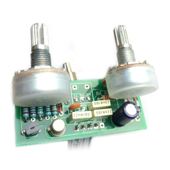
- Page 3 The power and signal pads on the PCB conform to the FuzzDog Direct Connection format, so can be paired with the appropriate daughterboard for quick and easy offboard wiring. Be very careful when soldering the diodes and transistors. They’re very sensitive to heat.
- Page 4 Test the board! A A T our nic e, ne w cir cuit boa INCL UDING WIRED PO !!!! UNDER NO CIRCUMSTANCES will troubleshooting help be offered if you have skipped this stage. No exceptions. Once you’ve finished the circuit it makes sense to test is before starting on the switch and LED wiring.
- Page 5 Wire it up - with battery (if using a daughterboard please refer to the relevant document) BOARD BOARD INPUT BOARD BOARD BOARD BOARD LED+ BOARD BOARD BATTERY This circuit is standard, Negative GND. Your power supply should be Tip Negative / Sleeve Positive. That’s the same as your standard pedals (Boss etc), and you can safely daisy-chain your supply to this pedal.
- Page 6 Wire it up - DC only version (if using a daughterboard please refer to the relevant document) BOARD BOARD INPUT BOARD BOARD BOARD BOARD LED+ BOARD BOARD This circuit is standard, Negative GND. Your power supply should be Tip Negative / Sleeve Positive. That’s the same as your standard pedals (Boss etc), and you can safely daisy-chain your supply to this pedal.
Need help?
Do you have a question about the Jordan Bosstone and is the answer not in the manual?
Questions and answers