Advertisement
Quick Links
Advertisement

Subscribe to Our Youtube Channel
Related Manuals for FuzzDog Bionic GuzzFun


Summary of Contents for FuzzDog Bionic GuzzFun
- Page 1 Bionic GuzzFun 5 knobs of sonic mayhem and an oscillation switch too PedalParts.co.uk...
- Page 2 Schematic 910K 100n 180K Q1,2* 2N5089 910K 470p 2N5306 910K 4.7u 4.7u DENS 100KB 180K 100n FUZZ 10KB 330n FILT 10KB 910K BIAS 50KB 750R S1-3 SPDT 100KA *The stock transistors give highly variable, very gated results, which may not be to everyone’s taste.
- Page 3 Snap the little metal tags off the pots to mount them flush in the box. You MUST use some kind of heat sink on the legs of the transistors when soldering. They aren’t keen on heat. Any more than 3-4 seconds of iron and they’re toast.
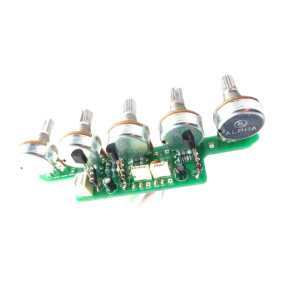
- Page 4 Test the board! BATTERY 9V GND Your nice, new circuit board INCLUDING WIRED POTS!!!! Once you’ve finished the circuit it makes sense to test is before starting on the switch and LED wiring. It’ll cut down troubleshooting time in the long run. If the circuit works at this stage, but it doesn’t once you wire up the switch - guess what? You’ve probably made a mistake with the switch.
- Page 5 Wire it up - DC only version BOARD BOARD INPUT BOARD BOARD BOARD BOARD LED+ BOARD BOARD There are GND connections for both jacks at either end of the board. All the GND pads are connected to each other in the traces on the PCB, and all of them are connected to both sides of the board.
- Page 6 Wire it up - with battery BOARD BOARD INPUT BOARD BOARD BOARD BOARD LED+ BOARD Just because our pre-drilled BOARD enclosure doesn’t BATTERY accommodate a battery, it doesn’t mean you can’t add one yourself in a bigger box. Follow this! There are GND connections for both jacks at either end of the board.
- Page 7 Oscillation Switch Maybe you want the oscillation mode on a footswitch...? Wire it as above and your extra LED will light up when oscillation is engaged. If you’re using DPDT (footswitch or toggle switch) just pretend that middle row isn’t there. You can use a footswitch daughterboard if you want to neatly mount the LED for the oscillation.
- Page 8 Drill template - 1590B Please check positioning before drilling - those holes are your responsibility and these templates are just a guide. The best way to mark holes for the pots is to lay the PCB on the box before you start soldering anything and mark at the centre pad of each. The DC socket needs to be quite close to the edge of the box so it comfortably clears the pots.
- Page 9 Drill template - 1590BB See previous page for notes on sizes etc. Drill EITHER the second footswitch OR the mini toggle switch, depending on which you’re using for the oscillation mode. PedalParts.co.uk...
Need help?
Do you have a question about the Bionic GuzzFun and is the answer not in the manual?
Questions and answers