
Related Manuals for FuzzDog 4-Track Fuzz


Summary of Contents for FuzzDog 4-Track Fuzz
- Page 1 4-Track Fuzz Like cranking the input on a Portastudio, apparently Contents of this document are ©2017 Pedal Parts Ltd. No reproduction permitted without the express written permission of Pedal Parts Ltd. All rights reserved.
- Page 2 Schematic + BOM 220n 1N4001 100K 100K 4558 470K 470R 100KA BASS 100KB 100n TREB 500KB TRIM 25KB 47u elec 100u elec CLR (2K2) 100R...
- Page 3 The power and signal pads on the PCB Positive (anode) legs of the electrolytic conform to the FuzzDog Direct Connection caps go to the square pads. format, so can be paired with the Negative (cathode) legs of the diodes go to appropriate daughterboard for quick and the square pad.
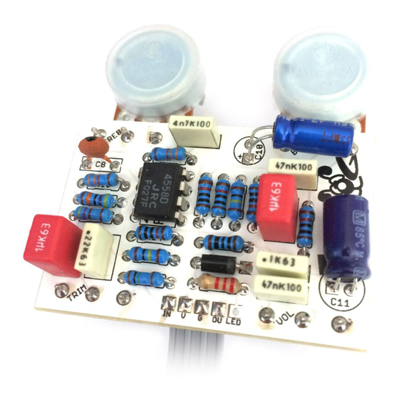
- Page 4 Test the board! BATTERY 9V GND Your nice, new circuit board INCLUDING WIRED POTS!!!! UNDER NO CIRCUMSTANCES will troubleshooting help be offered if you have skipped this stage. No exceptions. Once you’ve finished the circuit it makes sense to test is before starting on the switch and LED wiring.
- Page 5 Wire it up (if using a daughterboard please refer to the relevant document) BOARD BOARD INPUT BOARD BOARD BOARD BOARD LED+ BOARD BOARD BATTERY Wiring shown above will disconnect the battery when you remove the jack plug from the input, and also when a DC plug is inserted. The Board GND connections don’t all have to directly attach to the board.
-
Page 6: Drilling Template
3 mm This template is a rough guide only. You should ensure correct marking of your enclosure before drilling. You use this template at your own risk. Pedal Parts Ltd can accept no responsibility for incorrect drilling of enclosures. FuzzDog.co.uk...
Need help?
Do you have a question about the 4-Track Fuzz and is the answer not in the manual?
Questions and answers