
Related Manuals for Nexcom AIEdge-X 500


Summary of Contents for Nexcom AIEdge-X 500
- Page 1 NEXCOM International Co., Ltd. Intelligent Platform & Services Business Unit AI Edge Computer AIEdge-X ® User Manual NEXCOM International Co., Ltd. www.nexcom.com Published August 2021...
-
Page 2: Table Of Contents
COM Port Connector ..............16 Hardware Specifications ................2 COM Port Connector ..............17 Physical Features ..................4 COM Port Connector ..............17 Mechanical Dimensions ................5 SATA Connector ................18 SATA Connector ................18 Copyright © 2021 NEXCOM International Co., Ltd. All Rights Reserved. AIEdge-X ® 500 User Manual... - Page 3 Default Configuration ................35 Entering Setup ..................35 Legends ....................35 BIOS Setup Utility ..................37 Main ....................37 Advanced ..................38 Chipset ....................48 Security .....................50 Boot ....................50 Save & Exit ..................51 Copyright © 2021 NEXCOM International Co., Ltd. All Rights Reserved. AIEdge-X ® 500 User Manual...
-
Page 4: Preface
No describes how to keep the system CE compliant. part of this manual may be reproduced, copied, translated or transmitted in any form or by any means without the prior written consent from NEXCOM Declaration of Conformity International Co., Ltd. -
Page 5: Rohs Compliance
(Cr6+) < 0.1% or 1,000ppm, Polybrominated biphenyls (PBB) < 0.1% or 1,000ppm, and Polybrominated diphenyl Ethers (PBDE) < 0.1% or 1,000ppm. In order to meet the RoHS compliant directives, NEXCOM has established an engineering and manufacturing task force to implement the introduction of green products. -
Page 6: Warranty And Rma
“NEXCOM RMA Service Form” for the RMA number apply process. ▪ If RMA goods can not be repaired, NEXCOM will return it to the customer without any charge. ▪ Customers can send back the faulty products with or without accessories (manuals, cable, etc.) and any components from the card, such as CPU... - Page 7 ESD workstation. If no such station is available, you can provide some ESD protection by wearing an antistatic wrist strap and attaching it to a metal part of the computer chassis. Copyright © 2021 NEXCOM International Co., Ltd. All Rights Reserved. AIEdge-X ®...
-
Page 8: Safety Information
There is a danger of explosion if battery is incorrectly replaced. Replace only with the same or equivalent type recommended by the manufacturer. Discard used batteries according to the manufacturer’s instructions. viii Copyright © 2021 NEXCOM International Co., Ltd. All Rights Reserved. AIEdge-X ® 500 User Manual... -
Page 9: Safety Precautions
10. All cautions and warnings on the equipment should be noted. 18. Ensure to connect the power cord of the power adapter to a socket- outlet with earthing connection. Copyright © 2021 NEXCOM International Co., Ltd. All Rights Reserved. AIEdge-X ®... -
Page 10: Technical Support And Assistance
Preface Technical Support and Assistance Conventions Used in this Manual 1. For the most updated information of NEXCOM products, visit NEXCOM’s Warning: website at www.nexcom.com. Information about certain situations, which if not observed, can cause personal injury. This will prevent injury to yourself 2. -
Page 11: Global Service Contact Information
Shanghai, 201108, China Taichung City, 406, Taiwan, R.O.C. Email: sales@nexcom.com.tw Tel: +86-21-5278-5868 Tel: +886-4-2249-1179 www.nexcom.com.tw Fax: +86-21-3251-6358 Fax: +886-4-2249-1172 Email: sales@nexaiot.com Email: sales@nexcom.cn www.nexaiot.com www.nexcom.cn Copyright © 2021 NEXCOM International Co., Ltd. All Rights Reserved. AIEdge-X ® 500 User Manual... - Page 12 9F, Tamachi Hara Bldg., Chongqing City, 402160, China 4-11-5, Shiba Minato-ku, Tel: +86-23-4960-9080 Tokyo, 108-0014, Japan Fax: +86-23-4966-5855 Tel: +81-3-5419-7830 Email: sales@nexgol.com.cn Fax: +81-3-5419-7832 www.nexcobot.com/NexGOL Email: sales@nexcom-jp.com www.nexcom-jp.com Copyright © 2021 NEXCOM International Co., Ltd. All Rights Reserved. AIEdge-X ® 500 User Manual...
-
Page 13: Package Contents
500 package that you received ® is complete. Your package should have all the items listed in the following table. Item Name Thermal Pad Screw Carton xiii Copyright © 2021 NEXCOM International Co., Ltd. All Rights Reserved. AIEdge-X ® 500 User Manual... -
Page 14: Ordering Information
® AIEdge-X ® 500 (P/N: 10W20X5000X0) Industrial AI Computer powered by 8th/9th Generation Intel Core™ processor, ® with large storage and optional NVIDIA graphics card Copyright © 2021 NEXCOM International Co., Ltd. All Rights Reserved. AIEdge-X ® 500 User Manual... -
Page 15: Chapter 1: Product Introduction
▪ Suitable for all kinds of AI applications ▪ 1 x Intel I219-LM GbE PHY and 1 x Intel I211 Gigabit Ethernet Controller ® ® ▪ Supports Intel ® Copyright © 2021 NEXCOM International Co., Ltd. All Rights Reserved. AIEdge-X ® 500 User Manual... -
Page 16: Hardware Specifications
Storage unbuffered memory up to 64G (single socket max. 32GB) ▪ 4 x SATA 2.5” HDD/SSD with RAID 0/1/5/10 ▪ M.2 2280 Key M (SATA/PCIe) Copyright © 2021 NEXCOM International Co., Ltd. All Rights Reserved. AIEdge-X ® 500 User Manual... - Page 17 ▪ CE Approval ▪ FCC Class A ▪ LVD Dimensions ▪ 360mm x 290mm x 150mm (L x W x H) Operating System ▪ Windows 10/Linux Copyright © 2021 NEXCOM International Co., Ltd. All Rights Reserved. AIEdge-X ® 500 User Manual...
-
Page 18: Physical Features
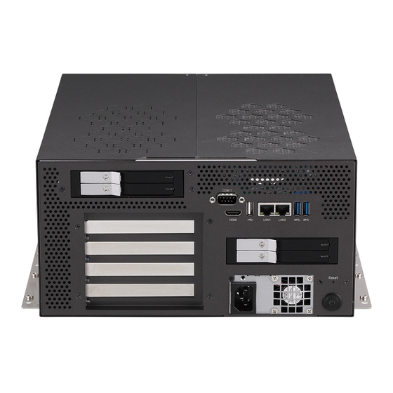
1 x PCIe x16 Slot 1 x PCIe x4 Slot 1 x PCI Slot AC Power Power Button Reset Button (2-Slot Space for GPU) Socket Copyright © 2021 NEXCOM International Co., Ltd. All Rights Reserved. AIEdge-X ® 500 User Manual... -
Page 19: Mechanical Dimensions
Chapter 1: Product Introduction Mechanical Dimensions 319.68 Copyright © 2021 NEXCOM International Co., Ltd. All Rights Reserved. AIEdge-X ® 500 User Manual... -
Page 20: Chapter 2: Jumpers And Connectors
Static electricity can damage many of the electronic ▪ Use correct screws and do not over tighten screws. components. Humid environments tend to have less static electricity than Copyright © 2021 NEXCOM International Co., Ltd. All Rights Reserved. AIEdge-X ®... -
Page 21: Jumper Settings
(on) and open (off). Two-Pin Jumpers: Open (Left) and Short (Right) Three-Pin Jumpers: Pins 1 and 2 are Short Copyright © 2021 NEXCOM International Co., Ltd. All Rights Reserved. AIEdge-X ® 500 User Manual... -
Page 22: Locations Of The Jumpers And Connectors For Aiedge-X ® 500
500. It shows the locations of the jumpers and connectors. ® Top View ATX12V_PWR1 USB2_2 USB2_1 USB2_3 COM3 CPUF SATA1 JFP1 SATA4 COM2 SYSF GPIO SATA3 COM4 COM1 SATA2 DEBUG SPWR1 SPWR2 Copyright © 2021 NEXCOM International Co., Ltd. All Rights Reserved. AIEdge-X ® 500 User Manual... -
Page 23: Bottom View
Chapter 2: Jumpers and Connectors Bottom View M2M_2280 Copyright © 2021 NEXCOM International Co., Ltd. All Rights Reserved. AIEdge-X ® 500 User Manual... -
Page 24: Jumpers
AT/ATX Mode Select Connector type: 1x3 3-pin header, 2.54mm pitch Connector location: ATATX Settings 1-2 On AT Mode 2-3 On ATX Mode 2-3 On: default Copyright © 2021 NEXCOM International Co., Ltd. All Rights Reserved. AIEdge-X ® 500 User Manual... -
Page 25: Internal Connectors
Connector type: 2x4 8-pin header, 2.54mm pitch Connector location: SPI Connector location: JFP1 Definition Definition Definition Definition S_RTCRST# HDD_LED PWR_LED +3V3_SPI HDD_LED# SPI_CS#_R SPI_CLK_R SHB_PWR_BTN# SPI_DO_R SPI_DI_R SHB_RST_BTN# Copyright © 2021 NEXCOM International Co., Ltd. All Rights Reserved. AIEdge-X ® 500 User Manual... -
Page 26: Dc In Connector
12V Power Connector Connector type: 1x3 3-pin Wafer, 3.96mm pitch Connector type: 2x2 4-pin header, 3.5mm pitch Connector location: 5PW Connector location: ATX12V_PWR1 Definition Definition +12V +12V Copyright © 2021 NEXCOM International Co., Ltd. All Rights Reserved. AIEdge-X ® 500 User Manual... -
Page 27: Cpu Fan Connector
Connector type: 1x4 4-pin Wafer, 2.54mm pitch Connector type: 1x4 4-pin Wafer, 2.54mm pitch Connector location: CPUF Connector location: SYSF Definition Definition +12V +12V FANIN1 FANIN2 FANOUT1 FANOUT2 Copyright © 2021 NEXCOM International Co., Ltd. All Rights Reserved. AIEdge-X ® 500 User Manual... -
Page 28: Gpio Connector
Connector location: GPIO Connector location: USB2_1 Definition Definition Definition Definition +5VGPIO +5V_USB2_12 +5V_USB2_12 GPIO70 GPIO71 USB2N_5 USB2N_6 GPIO72 GPIO73 USB2P_5 USB2P_6 GPIO74 GPIO75 GPIO76 GPIO77 Copyright © 2021 NEXCOM International Co., Ltd. All Rights Reserved. AIEdge-X ® 500 User Manual... -
Page 29: Usb Connector
Connector type: 2x5 10-pin header, 2.54mm pitch Connector location: USB2_2 Connector location: USB2_3 Definition Definition Definition Definition +5V_USB2_12 +5V_USB2_12 +5V_USB2_34 +5V_USB2_34 USB2N_7 USB2N_8 USB2N_9 USB2N_10 USB2P_7 USB2P_8 USB2P_9 USB2P_10 Copyright © 2021 NEXCOM International Co., Ltd. All Rights Reserved. AIEdge-X ® 500 User Manual... -
Page 30: Com Port Connector
Connector location: COM1 Connector location: COM2 Definition Definition Definition Definition COM_RI# COM_CTS# COM_RI# COM_CTS# COM_RTS# COM_DSR# COM_RTS# COM_DSR# COM_DTR# COM_DTR# COM_TXD COM_RXD COM_TXD COM_RXD COM_DCD# COM_DCD# Copyright © 2021 NEXCOM International Co., Ltd. All Rights Reserved. AIEdge-X ® 500 User Manual... -
Page 31: Com Port Connector
Connector location: COM3 Connector location: COM4 Definition Definition Definition Definition COM_RI# COM_CTS# COM_CTS# COM_RTS# COM_DSR# COM_RTS# COM_DSR# COM_DTR# COM_DTR# COM_TXD COM_RXD COM_TXD COM_RXD COM_DCD# COM_DCD# Copyright © 2021 NEXCOM International Co., Ltd. All Rights Reserved. AIEdge-X ® 500 User Manual... -
Page 32: Sata Connector
Connector type: Standard Serial ATA 7P (1.27mm, SATA-M-180) Connector location: SATA1 Connector location: SATA2 Definition Definition Definition Definition S_SATA_TXP0 S_SATA_TXP1 S_SATA_TXN0 S_SATA_TXN1 S_SATA_RXN0 S_SATA_RXP0 S_SATA_RXN1 S_SATA_RXP1 Copyright © 2021 NEXCOM International Co., Ltd. All Rights Reserved. AIEdge-X ® 500 User Manual... -
Page 33: Sata Connector
Connector type: Standard Serial ATA 7P (1.27mm, SATA-M-180) Connector location: SATA3 Connector location: SATA4 Definition Definition Definition Definition S_SATA_TXP2 S_SATA_TXP3 S_SATA_TXN2 S_SATA_TXN3 S_SATA_RXN2 S_SATA_RXP2 S_SATA_RXN3 S_SATA_RXP3 Copyright © 2021 NEXCOM International Co., Ltd. All Rights Reserved. AIEdge-X ® 500 User Manual... -
Page 34: Sata Power Connector
SATA Power Connector Connector type: 1x2 2-pin header JST, 2.5mm pitch Connector type: 1x2 2-pin header JST, 2.5mm pitch Connector location: SPWR1 Connector location: SPWR2 Definition Definition Copyright © 2021 NEXCOM International Co., Ltd. All Rights Reserved. AIEdge-X ® 500 User Manual... -
Page 35: 80 Port Connector
Chapter 2: Jumpers and Connectors 80 Port Connector Connector type: 1x10 10-pin header, 1.0mm pitch Connector location: DEBUG Definition Definition PLTRST#_BUFF_1 CLKOUT_LPC1 LFRAME# LPC_D3 LPC_D2 LPC_D1 LPC_D0 SERIRQ_R +3V3 Copyright © 2021 NEXCOM International Co., Ltd. All Rights Reserved. AIEdge-X ® 500 User Manual... -
Page 36: Connector (M-Key)
+3VSB PCIE_TXP17 PERST#1 PCIE_TXP20 +3VSB +3VSB SRCCLKREQ_N11 S_PCIE_RXN19 +3VSB S_CLKOUT_PCIE_N11 PEWAKE_N1 S_PCIE_RXP19 S_CLKOUT_PCIE_P11 PCIE_TXN19 PCIE_TXP19 SUSCLK2 S_PCIE_RXN18 PEDET_1 +3VSB S_PCIE_RXP18 +3VSB +3VSB PCIE_TXN18 PCIE_TXP18 DEVSLP_0 Copyright © 2021 NEXCOM International Co., Ltd. All Rights Reserved. AIEdge-X ® 500 User Manual... -
Page 37: Chapter 3: System Setup
1. Remove the six mounting screws around the chassis. Copyright © 2021 NEXCOM International Co., Ltd. All Rights Reserved. AIEdge-X ® 500 User Manual... - Page 38 Chapter 3: System Setup 2. Slide out the two top covers, then lift up the covers to remove them. Copyright © 2021 NEXCOM International Co., Ltd. All Rights Reserved. AIEdge-X ® 500 User Manual...
-
Page 39: Installing A Memory Module
1. With the two top covers removed, loosen the four screws on the heat 2. Release the locks on the memory slots. sink fan, then remove it to access the memory slots. Copyright © 2021 NEXCOM International Co., Ltd. All Rights Reserved. AIEdge-X ®... - Page 40 3. Insert the module into the socket at a 90 degree angle. Apply firm even pressure to each end of the module until it slips into the slot. While pushing the module into position, the locks will close automatically. Copyright © 2021 NEXCOM International Co., Ltd. All Rights Reserved. AIEdge-X ®...
-
Page 41: Installing A Cpu
1. With the two top covers removed, loosen the four screws on the heat 2. The CPU socket is readily accessible after you have removed the heat sink. sink fan, then remove the heat sink. CPU Socket Copyright © 2021 NEXCOM International Co., Ltd. All Rights Reserved. AIEdge-X ® 500 User Manual... - Page 42 CPU socket. Load Lever Retention Tab Copyright © 2021 NEXCOM International Co., Ltd. All Rights Reserved. AIEdge-X ® 500 User Manual...
- Page 43 ▪ Handle the CPU by its edges and avoid touching the pins. ▪ The CPU will fit in only one orientation and can easily be inserted without exerting any force. Copyright © 2021 NEXCOM International Co., Ltd. All Rights Reserved. AIEdge-X ®...
- Page 44 7. Hook the load lever under the retention tab. 8. Reinstall the CPU heat sink fan with the four mounting screws removed earlier. Retention Load Lever Copyright © 2021 NEXCOM International Co., Ltd. All Rights Reserved. AIEdge-X ® 500 User Manual...
-
Page 45: Installing An Add-On Card
1. Remove the two screws on the brackets as shown below, then plug the add-on card (using a graphics card as an example in the following steps) into the PCIe slot. Copyright © 2021 NEXCOM International Co., Ltd. All Rights Reserved. AIEdge-X ®... - Page 46 2. Plug in the 6+2-pin power cable for the graphics card if necessary, then refasten the two screws on the graphics card bracket to secure the card firmly. Copyright © 2021 NEXCOM International Co., Ltd. All Rights Reserved. AIEdge-X ®...
-
Page 47: Installing A 2.5" Storage Drive (External)
Once the storage drive is fully seated accessory pack. inside the drive bay, close and resecure the cover. Copyright © 2021 NEXCOM International Co., Ltd. All Rights Reserved. AIEdge-X ® 500 User Manual... -
Page 48: Chapter 4: Bios Setup
BIOS is updated in the future. second, to make settings appropriate for the way you use the computer. To check for the latest updates and revisions, visit the NEXCOM website at When to Configure the BIOS www.nexcom.com.tw. -
Page 49: Default Configuration
Setup. Load optimized default values. Press the key to enter Setup: Saves and exits the Setup program. Press <Enter> to enter the highlighted sub-menu Copyright © 2021 NEXCOM International Co., Ltd. All Rights Reserved. AIEdge-X ® 500 User Manual... - Page 50 When “” appears on the left of a particular field, it indicates that a submenu which contains additional options are available for that field. To display the submenu, move the highlight to that field and press Copyright © 2021 NEXCOM International Co., Ltd. All Rights Reserved. AIEdge-X ®...
-
Page 51: Bios Setup Utility
2400 MHz F3: Optimized Defaults F4: Save & Exit PCH Information ESC: Exit PCH SKU Q370 Stepping ▼ Version 2.20.1275. Copyright (C) 2020 American Megatrends, Inc. Copyright © 2021 NEXCOM International Co., Ltd. All Rights Reserved. AIEdge-X ® 500 User Manual... -
Page 52: Advanced
F4: Save & Exit Active Processor Cores ESC: Exit Select the number of cores to enable in each processor package. Version 2.20.1275. Copyright (C) 2020 American Megatrends, Inc. Copyright © 2021 NEXCOM International Co., Ltd. All Rights Reserved. AIEdge-X ® 500 User Manual... - Page 53 C states Enable CPU C States Support for power saving. It is recommended to keep C3, C6 and C7 all enabled for better power saving. Copyright © 2021 NEXCOM International Co., Ltd. All Rights Reserved. AIEdge-X ® 500 User Manual...
- Page 54 Enables or disables ME state. When disabled, ME will be placed into ME Temporarily Disabled Mode. Manageability Features State Enables or disables Manageability Features State. Copyright © 2021 NEXCOM International Co., Ltd. All Rights Reserved. AIEdge-X ® 500 User Manual...
- Page 55 Enables or disables Alert Standard Format support. Enables or disables the ME firmware image re-flash function. USB Provisioning of AMT Enables or disables USB Provisioning of AMT. Copyright © 2021 NEXCOM International Co., Ltd. All Rights Reserved. AIEdge-X ® 500 User Manual...
- Page 56 TPM 2.0 devices if not found, and TPM 1.2 devices will be Enables or disables SHA-1 PCR Bank. enumerated. SHA256 PCR Bank Enables or disables SHA256 PCR Bank. Copyright © 2021 NEXCOM International Co., Ltd. All Rights Reserved. AIEdge-X ® 500 User Manual...
- Page 57 Version 2.20.1275. Copyright (C) 2020 American Megatrends, Inc. Super IO Chip Serial Port Enables or disables the serial port. Displays the Super I/O chip used on the board. Copyright © 2021 NEXCOM International Co., Ltd. All Rights Reserved. AIEdge-X ® 500 User Manual...
- Page 58 CPU FAN and SYSTEM FAN Detects and displays the current fan speed of the CPU fan and system fan. Vcore to +3V3 Detects and displays the output voltages. Copyright © 2021 NEXCOM International Co., Ltd. All Rights Reserved. AIEdge-X ® 500 User Manual...
- Page 59 Enables or disables system wake on alarm event. When FixedTime is selected, system will wake on the hr::min::sec specified. When DynamicTime is selected, system will wake on the current time + Increase minute(s). Copyright © 2021 NEXCOM International Co., Ltd. All Rights Reserved. AIEdge-X ®...
- Page 60 XHCI Hand-off This is a workaround for OSs that does not support XHCI hand-off. The XHCI ownership change should be claimed by the XHCI driver. Copyright © 2021 NEXCOM International Co., Ltd. All Rights Reserved. AIEdge-X ® 500 User Manual...
- Page 61 ESC: Exit Version 2.20.1275. Copyright (C) 2020 American Megatrends, Inc. Version 2.20.1275. Copyright (C) 2020 American Megatrends, Inc. Network Stack Enables or disables UEFI network stack. Copyright © 2021 NEXCOM International Co., Ltd. All Rights Reserved. AIEdge-X ® 500 User Manual...
-
Page 62: Chipset
Version 2.20.1275. Copyright (C) 2020 American Megatrends, Inc. PEG Port Configuration System Agent (SA) Configuration Enters the PEG Port Configuration submenu. System Agent (SA) parameters. PCH-IO Configuration PCH-IO parameters. Copyright © 2021 NEXCOM International Co., Ltd. All Rights Reserved. AIEdge-X ® 500 User Manual... - Page 63 Enables or disables integrated LAN to wake the system. State After G3 Configures the power state when power is re-applied after a power failure (G3 state). Copyright © 2021 NEXCOM International Co., Ltd. All Rights Reserved. AIEdge-X ® 500 User Manual...
-
Page 64: Security
Adjust the boot sequence of the system. Boot Option #1 is the first boot device that the system will boot from, next will be #2 and so forth. Copyright © 2021 NEXCOM International Co., Ltd. All Rights Reserved. AIEdge-X ®... -
Page 65: Save & Exit
Boot Override To bypass the boot sequence from the Boot Option List and boot from a particular device, select the desired device and press <Enter>. Copyright © 2021 NEXCOM International Co., Ltd. All Rights Reserved. AIEdge-X ® 500 User Manual...
Need help?
Do you have a question about the AIEdge-X 500 and is the answer not in the manual?
Questions and answers