Advertisement
Available languages
Available languages
Quick Links
INSTRUCTION
EN
NRT405F902
Instruction for products with software version
i
1.2. Read this instruction before installation and
wiring of the product.
Consult documentation in all cases where this symbol
is used, in order to find out the nature of the potential
hazards and any actions to be taken
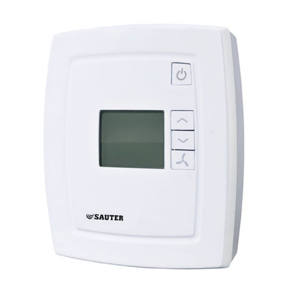
Room controller for controlling fan-coil units
NRT405F902 is a room controller intended for controlling fan-coil
heaters/coolers and actuators with 0...10 V control signal. Installation
is directly on the wall or on an electrical connection box. The fan can
be set to one of three speeds.
NRT405F902 has change-over function and can be used for 2-pipe or
4-pipe systems.
For integration into a system, NRT405F902 has communication via
RS485 (Modbus or BACnet). The device can be configured using the
application NRT tool (version 1.3-1-05 or later), which can be down-
loaded from the SAUTER ITALIA SPA web site (www.sauteritalia.it).
Technical data
Supply voltage
230 V AC ±10 %, 50/60 Hz
Power consumption
< 3 W
Ambient temperature
0...50°C
Ambient humidity
Max 90 % RH
Storage temperature
-20...+70°C
Built-in temperature sensor NTC type, range 0...50°C
Inputs
Refer to connection illustrations and
table below
Outputs
Relays for fan control, 230 V AC, 3 A
AO1, AO2, 0...10 V DC
Communication
RS485: Modbus (using automatic detection/
switching) or BACnet
Modbus
8 bits, 1 or 2 stop bits. Odd, even
(FI) or no parity
Communication speed
9600, 19200, 38400 bps (Modbus and
BACnet) or 76800 bps (BACnet only)
Terminal blocks
Lift type for a maximum cable area 2.1 mm
Protection class
IP20
Pollution degree
2
Overvoltage category
3
Material casing
Polycarbonate, PC
Dimensions
102 x 120 x 29 mm
Installation
Place the controller in a location that has a temperature representative for
the room. A suitable location is approx. 1.6 m above floor level in a place
with unobstructed air circulation.
Depress the locking tab in the upper edge of the controller with a
screwdriver. Carefully turn the screwdriver until the bottom plate and the
electronics unit are slightly separated (see figure 1). Then use the cutout
that becomes visible in the edge of the bottom plate to open the upper
edge completely (see figure 2). Do the same thing in the lower edge of the
controller.
Figure 1
Figure 2
Lift the electronics unit up from the bottom plate. The bottom plate with
terminals has a number of hole combinations. Select suitable holes and
fasten the bottom plate on the wall or connection box, so that the arrows
on the bottom plate point upwards. Do not tighten the screws too hard!
NRT405F902
Disconnection
NRT405F902 should be connected to a switch or circuit breaker in
the building installation. This switch should be in close proximity to
the controller and within easy reach of the operator, and should be
marked as the disconnecting device for the equipment.
Always use the circuit breaker to disconnect the controller from the
mains supply during maintenance of the fan-coil and actuators.
Settings
Control modes
NRT405F902 can control heating and cooling in sequence or be set
to seasonal switching between heating and cooling (change-over, see
2
below).
Change-over function
NRT405F902 has an input for change-over that automatically sets the
output AO1 to operate with heating or cooling function. A sensor of
type PT1000 can be connected to the input and must be mounted so
that it senses the temperature on the supply pipe to the coil.
When the temperature exceeds 28°C, the output function is set to
heating and when the temperature drops below 16°C, the output is
set to cooling. As an alternative, a potential-free contact can be used.
The input function can be set to NO/NC.
To ensure satisfactory functioning when using a sensor, the system
must have continuous primary circuit circulation. When the change-
over function is not used, the input must be left disconnected.
Operating mode
There are four different operating modes. Switching between these
modes is performed locally.
Comfort:
is shown in the display. Heating and cooling have a
smaller neutral zone NZC. An occupancy detector can be connected
to the DI in order to select between Comfort and Economy. Switching
between Comfort/Economy and Off can also be done via the On/Off
button. Comfort/Economy is selected via the parameter list.
Economy (Standby): "Standby" is shown in the display. The heat-
ing and cooling setpoints are freely adjustable. Factory settings:
heating=15°C, cooling=30°C.
Off: The controller does not heat or cool and the fan stops (unless
mould protection has been selected, in which case the fan will still
run).
Window:
is shown in the display, the controller is off and the fan
stops (unless mould protection has been selected, in which case the
fan will still run). The window contact is connected to the DI and must
be configured.
1
Advertisement

Related Manuals for sauter NRT405F902


Summary of Contents for sauter NRT405F902
- Page 1 Storage temperature -20...+70°C Disconnection Built-in temperature sensor NTC type, range 0...50°C NRT405F902 should be connected to a switch or circuit breaker in Inputs Refer to connection illustrations and the building installation. This switch should be in close proximity to table below...
- Page 2 On/Off button. You can also exit the parameter list by pressing 0=0...10V, 1=2...10V, 2=10...2V, 3=10...0V The fan can be controlled via NRT405F902 with the following modes: down the INCREASE and DECREASE buttons simultaneously. Output signal for actuator connected to AO2: Low speed, Medium speed, High speed, Auto.
- Page 3 0=NO, 1=NC 1=Factory settings (Modbus@9600) Not used for this model Basic setpoint. Settable value=5...50°C. 22°C Not used for this model Manual/Auto heating output signal: 0=Off, 1=Manual, 2=Auto Manual/Auto cooling output signal: 0=Off, 1=Manual, 2=Auto Figure 5: Connection diagram NRT405F902...
- Page 4 Digital input Potential-free window contact impostata su una velocità tra le tre disponibili. or occupancy contact. Con- NRT405F902 è dotato di una funzione di commutazione e può essere figurable for NO/NC. usato per sistemi a 2 o 4 tubi. Agnd Analogue ground Per l’integrazione in un sistema, NRT405F902 è...
-
Page 5: Installazione
Classe di protezione IP20 one. Il parametro 24 determina ciò che viene visualizzato nel display. NRT405F902 è in grado di controllare il riscaldamento e il raffreddamento Grado d’inquinamento Per informazioni dettagliate, fare riferimento all’elenco dei parametri. in sequenza o essere impostato per il cambio stagionale tra riscaldamento Categoria di sovratensione e raffreddamento (commutazione, vedere di seguito). - Page 6 Pulsante On/Off un surriscaldamento del riscaldatore. zona neutra è 2 K, il setpoint di riscaldamento Premendo il pulsante On/Off, NRT405F902 passa dalla modalità equivale al setpoint meno 1, mentre il setpoint di Segnale avvio in % dell'uscita del regolatore, 20 (5 Disattivazione alla modalità...
- Page 7 0 a 10 V *La somma della corrente attraverso DO1-DO3 viene protetta da un 1=Impostazioni di fabbrica fusibile (Modbus@9600) 230 V CA Setpoint di base. Valore regolabile=da 5 a 50 °C. 22 °C Commutazione Figura 5: Schema di collegamento NRT405F902...
-
Page 8: Installation
Consiglio. Raumregler für Fan-Coil-Anlagen Contatti NRT405F902 ist ein Raumregler für die Regelung von Fan-Coils (mit Er- Sauter Italia S.p.A., Via Dei Lavoratori, hitzer/Kühler) und Stellantrieben mit 0...10 V-Ansteuerung. Die Installation 131 IT-20092 Cinisello Balsamo (MI), Italia erfolgt direkt an die Wand oder an eine Anschlussdose. - Page 9 Zone=2 K, ist der Sollwert Heizen= Parameterliste. Ein/Aus-Taste Basissollwert-1 und der Sollwert Kühlen = Basis- Bei Drücken der Ein/Aus-Taste schaltet NRT405F902 zwischen Abschalt- sollwert+1. Sollwertbegrenzung und Komfort/Eco-Modus um. Mit den Parameter 34 und 35 werden die Minimal- bzw. Maximalbe- SW Heizen bei keiner Präsenz.
- Page 10 2 ms für Start Ventilatorstufe 3 ein Zeichen sein, d.h. mindestens 2 ms. Hysterese für Ein-/Ausschalten der Ventilator- Modbus-Antwortverzögerung (t3,5) in ms. Sollte 5 ms stufen (in % des Stellsignals) 3,5 x ein Zeichen sein, d.h. mindestens 5 ms. NRT405F902...
- Page 11 électrique. Il permet de régler la vitesse des ventilateurs avec Analogausgang 1 trois vitesses disponibles. NRT405F902 est doté d’une fonction change-over et peut être utilisé Analogausgang 2 dans des installations à 2 ou 4 tubes.Pour l’intégration dans un RS485 Kommunikation A système, le NRT405F902 exploite le protocole de communication...
- Page 12 Degré de pollution Fonction change-over Limitation de la valeur de consigne Catégorie de surtension NRT405F902 est doté d’une entrée pour la fonction change-over qui Les paramètres 34 et 35 permettent de fixer le décalage maximum Matière, boîtier Polycarbonate, PC permet d’utiliser automatiquement la sortie AO1 en chauffage ou en autorisé...
- Page 13 Bouton de marche/arrêt Nº Description Nº Description Lorsque vous appuyez sur ce bouton, NRT405F902 passe du mode Mode de fonctionnement sur activation de DI1 : Choix du type d’information affiché à l’écran : Arrêt au mode Confort/Éco. 0=Mode Éco (détecteur de présence) 0=Valeur réelle, la consigne s’affiche lorsque cette...
- Page 14 Délai de réponse Modbus (t3.5) en ms. Doit être 5 ms ventilateur égal à 3,5 fois un caractère, c.-à-d. au moins 5 ms. Sortie 2 ventilo- Relais, 230 V AC*, 3 A convecteur. Protocole de communication : 0=Modbus, 1=BACnet MS/TP Commande ventilateur NRT405F902...
- Page 15 Ce produit répond aux exigences de la directive 2011/65/UE du Parlement européen et du Conseil. Contact Sauter Italia S.p.A., Via Dei Lavoratori, 131 IT-20092 Cinisello Balsamo (MI), Italia Tel: +39 02 280 481, Fax: +39 02 280 482 80 www.sauteritalia.it...
Need help?
Do you have a question about the NRT405F902 and is the answer not in the manual?
Questions and answers