Sign In
Upload
Manuals
Brands
Agilent Technologies Manuals
Laboratory Equipment
5517FL
Agilent Technologies 5517FL Manuals
Manuals and User Guides for Agilent Technologies 5517FL. We have
1
Agilent Technologies 5517FL manual available for free PDF download: User Manual
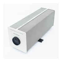
Agilent Technologies 5517FL User Manual (102 pages)
Laser Head
Brand:
Agilent Technologies
| Category:
Laboratory Equipment
| Size: 4.5 MB
Table of Contents
Table of Contents
7
1 General Information
15
Introduction
16
Description of the Agilent 5517B/BL/C/D/DL/FL
16
Laser Head
16
Description of the Agilent 5517B/BL/C/D/DL/FL Laser Head
16
Figure 1. Agilent 5517B/C/D and 5517BL/DL/FL Laser Heads
17
Table 1 Summary of the Laser Head Major Operating Characteristics
18
Table 2 Laser Head Mechanical and Electronic Assembly Summary
18
Manual Organization
19
Options
20
Table 3 Available Options
20
Accessories
21
Cables
21
Power Supply
21
Table 4 Laser Head Cables
22
Related Documents
23
2 Laser Head at a Glance
25
Laser Head Front Panel at a Glance
26
Laser Head Rear Panel at a Glance
27
3 Installation
29
Introduction
30
Preparing the Laser Head for Use
30
Unpacking and Inspection
30
Warranty Claims
31
Installing the Laser Head
31
Connecting the Laser Head Cables
32
Figure 2 Agilent 10881A/B/C Laser Head Cable
33
Figure 3 Agilent N1251B High Performance Laser Head Cable
34
Figure 4 Agilent 10881D/E/F Laser Head Cable
35
Table 5 Terminal Connections (Three Spade Lugs)
35
Figure 5 Agilent 10791A/B/C Laser Head Cable
36
Figure 6. Installation of Laser System Cables
37
Table 6 18-Pin Laser Head Cable and Rear Panel Connector Pin Assignments
38
Electrical Considerations
39
Grounding Considerations
39
Power Supply Requirements
39
Power Dissipation
39
Fusing
39
Table 7 Laser Head Power Supply Requirements
39
Figure 7 A1 Connector Board, Component Side, Showing Fuse Locations and High Voltage Connectors
40
Table 8 Laser Head Internal Fuses
40
Mounting Considerations
41
Orientation
41
Thermal Isolation
41
Figure 8 A3 Controller/Reference Board
41
Heat Flow Considerations
42
Vibration Isolation
42
Magnetic Shielding
42
Mounting Plane Tolerance
43
Mounting and Clearance
43
Figure 9 Laser Position Transducer Mounting
43
Powering up the Laser Head
44
4 Performance Tests
45
Introduction
46
Recommended Test Equipment
46
Table 9 Recommended Test Equipment
46
Performance Tests
47
Laser Power Output Test
47
Figure 10 Front Panel Turret and Aperture
47
Figure 11 Measuring the Laser Beam Power with Power Meter Detector
48
Split Frequency Test
49
Figure 12 Split Frequency Test Setup
49
Wavelength Test
50
Performance Test Record
51
5 Adjustments
53
Introduction
54
Safety Considerations
54
Recommended Test Equipment
55
Laser Head Adjustments
55
Equipment Needed
55
Preheat Setting
56
Table 10. Setpoint Voltages at TP11 and TP15 - Standard Tube with 05517-60031 A3
58
Table 11 Setpoint Voltages at A3TP11 and A3TP15 - Short Body Tube
59
Table 12. Setpoint Voltages at TP11 and TP15 - Standard Tube with 05517-60003 A3
60
Figure 13. Jumper Locations on A3 Controller/Reference Board (05517-60031)
61
Figure 14. Jumper Locations on A3 Controller/Reference Board (05517-60003)
61
Figure 15 High Voltage Area and Anode Lead
62
Figure 16 Three-Pin High Voltage Power Supply Connector
62
Adjustment Test Record
63
6 Using the Laser Head in a System
65
Introduction
66
A One-Axis Example Is Used for Simplicity
66
Basic Steps Apply to All Laser Systems
66
Agilent Laser Interferometer Positioning Systems at a Glance
66
All Agilent Laser Systems Share a Similar Configuration
67
Figure 17 Typical Single-Axis Agilent Laser Interferometer Positioning System
67
A Controller Is Required for All Laser Positioning Systems
68
Setting up the System Electronics
68
Install the Laser Electronics Board in the PC
68
Connect the Electronics Cables
68
Power up the Laser Head
69
Aligning the Optics
70
Making Measurements - an Example
71
Figure 18 Start/Programs Pop-Up Menu
71
Figure 19. Monitor Screen after Opening the Application
72
Figure 20 Measurement Screen
73
Solving Problems
74
7 Service
75
Introduction
76
Unpacking and Inspection
76
Warranty Claims
76
Contacting Agilent Technologies
76
Laser Head Shipment
77
Tagging for Service
77
Packaging for Reshipment
77
Laser Head Troubleshooting
78
Exchange Laser Tube Assemblies
78
Troubleshooting
78
Table 13 Exchange Laser Tube Assemblies
78
Figure 21 Laser Head-Primary Troubleshooting Flowchart
79
Figure 22 Board Trouble Isolation Flowchart
80
Figure 23 DS1 through DS4 Locations on A3 Controller/Reference Board
81
Figure 24 DS4, DS6, Q3, TP1 and TP8 Locations on A3 Controller/Reference Board
81
Disassembly Procedures
82
Tools Required
82
Table 14 Disassemble Procedures
82
To Remove the Front Panel and the Cover
83
Figure 25 Laser Head Cover Removal
83
To Remove the A3 Controller/Reference Board
84
To Remove the A1 Connector Board
84
To Remove the A4 Sampler Board
85
To Remove the A5 Laser Tube Assembly and A2 Power Supply
85
8 Specifications
87
Introduction
88
Calibration Cycle
88
Specifications and Characteristics
88
Table 15 Agilent Laser Head Specifications and Characteristics
89
Figure 26 Agilent 5517B/C/D Laser Head Dimensions and Mounting Location
92
Figure 27 Agilent 5517BL/DL/FL Laser Head Dimensions and Mounting Location
93
Index
95
Advertisement
Advertisement
Related Products
Agilent Technologies 5517B
Agilent Technologies 5517C
Agilent Technologies 5517D
Agilent Technologies 5517BL 5517C
Agilent Technologies 5517DL
Agilent Technologies 5975C TAD VL MSD
Agilent Technologies 5975T LTM GC/MSD
Agilent Technologies 5100 ICP-OES
Agilent Technologies 5110 ICP-OES
Agilent Technologies 5977 Series
Agilent Technologies Categories
Measuring Instruments
Laboratory Equipment
Test Equipment
Water Pump
Power Supply
More Agilent Technologies Manuals
Login
Sign In
OR
Sign in with Facebook
Sign in with Google
Upload manual
Upload from disk
Upload from URL