Pfeiffer Vacuum HIPACE 10 Operating Instructions Manual
Turbopump
Hide thumbs
Also See for HIPACE 10:
- Operating instructions manual (32 pages) ,
- Operating instructions manual (56 pages)
Table of Contents
Advertisement
Quick Links
Advertisement
Table of Contents

Related Manuals for Pfeiffer Vacuum HIPACE 10


Summary of Contents for Pfeiffer Vacuum HIPACE 10
- Page 1 OPERATING INSTRUCTIONS Original HIPACE 10 ► Turbopump...
- Page 2 Dear Customer, Thank you for choosing a Pfeiffer Vacuum product. Your new turbopump is designed to support you by its performance, its perfect operation and without interfering your individual application. The name Pfeiffer Vacuum stands for high-quality vacuum technology, a comprehensive and complete range of top-quality products and first-class service.
-
Page 3: Table Of Contents
Commissioning Operating modes 6.2.1 Operation without operating unit 6.2.2 Operation via multi-function connection "X3" 6.2.3 Operation via Pfeiffer Vacuum display and control unit 6.2.4 Operation via field bus Switching on the turbopump Operation monitoring 6.4.1 Operating mode display via LED... - Page 4 Replacing the electronic drive unit Confirming the rotation speed specification Decommissioning Shutting down for longer periods Recommissioning Disposing of the vacuum pump Malfunctions Service solutions from Pfeiffer Vacuum Spare parts HiPace 10 Accessories Technical data and dimensions 13.1 General 13.2 Technical data 13.3 Dimensions...
- Page 5 Tbl. 2: Abbreviations used in this document................9 Tbl. 3: Permissible ambient conditions................14 Tbl. 4: Product designation of Pfeiffer Vacuum HiPace turbopumps........16 Tbl. 5: Turbopump features....................16 Tbl. 6: Requirements for the dimensioning of customer-specific high vacuum connection..Tbl. 7: Behavior of the pumping speed using a mesh screen..........21...
- Page 6 Fig. 10: Operating fluid reservoir bearing side 1..............31 Fig. 11: Operating fluid reservoir bearing side 2..............32 Fig. 12: Installing and removing the electronic drive unit TC 110..........34 Fig. 13: Spare parts HiPace 10..................... 43 Fig. 14: HiPace 10 | TC 110 | DN 25 ISO-K................47 6/50...
-
Page 7: About This Manual
1.1 Validity ► These operating instructions are for customers of Pfeiffer Vacuum. They describe the function of the designated product and provide the most important information for safe usage of the product. The de- scriptions comply with applicable directives. All information provided in these operating instructions refer to the current development status of the product. -
Page 8: Abbreviations
Tbl. 1: Product stickers Fig. 1: Position of the stickers on the product ► Banner with Pfeiffer Vacuum logo Operating manual note Closure seal Rating plate Warning sign "Risk of injury with high vacuum connec- Information regarding ground connection tion open"... -
Page 9: Instructions In The Text
About this manual Abbreviation Meaning in this document Display Control Unit (Pfeiffer Vacuum display and control unit). Nominal diameter as size description Rotation speed value of a vacuum pump (frequency, in rpm or Hz) Handheld Programming Unit. Aid for control and monitoring of pump parameters... -
Page 10: Safety
Safety 2 Safety ► 2.1 General safety instructions ► This document includes the following four risk levels and one information level. DANGER Imminent danger Indicates a hazardous situation which, if not avoided, will result in death or serious injury. ► Instructions on avoiding the hazardous situation WARNING Possibly imminent danger Indicates a hazardous situation which, if not avoided, could result in death or serious injury. - Page 11 Safety Risks during installation DANGER ► Danger to life from electric shock Power supply packs that are not specified or are not approved will lead to severest injuries up to death. ► Make sure that the power supply pack meets the requirements for double isolation between mains input voltage and output voltage, in accordance with IEC 61010 and IEC 60950.
- Page 12 Safety Risks during operation WARNING ► Danger to life from electric shock in the event of a fault In the event of a fault, devices connected to the mains may be live. There is a danger to life from electric shock when making contact with live components. ►...
-
Page 13: Safety Precautions
► Follow the installation instructions for this turbopump. ► Observe the requirements regarding stability and design of the counter flange. ► Use only original accessories or fixing material approved by Pfeiffer Vacuum for the installation. WARNING ► Danger to life from poisoning where toxic process media leak from damaged connections Sudden twisting of the turbopump in the event of a fault causes fittings to accelerate. -
Page 14: Limits Of Use Of The Product
Safety Infringement of EU conformity due to modifications to the product ► The Declaration of Conformity from the manufacturer is no longer valid if the opera- tor changes the original product or installs additional equipment. ● Following installation into a system, the operator is required to check and re- evaluate as necessary the conformity of the overall system in the context of the relevant EU Directives before commissioning that system. -
Page 15: Proper Use
Safety 2.5 Proper use ► ► Use the turbopump only for generating vacuum. ► Use the turbopump only in combination with a suitable backing pump that can deliver up to the required maximum fore-vacuum pressure. ► Use the turbopump only in closed indoor areas. ►... -
Page 16: Product Description
HV flange DN 25 DN 40 Flange material Aluminium Aluminium Tbl. 5: Turbopump features 3.2 Functional properties ► The turbopump forms a compact unit with the electronic drive unit TC 110. The Pfeiffer Vacuum power supply packs serve as voltage supply. 16/50... -
Page 17: Cooling
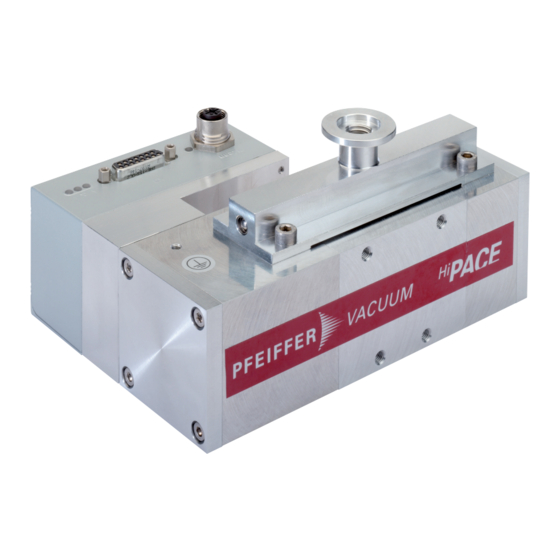
Product description Fig. 2: HiPace 10 design ► Electronic drive unit TC 110 Fore-vacuum connection adapter Screw caps (Bearing sides) Protective cover (fore-vacuum coonection) Pump housing Ground terminal Fixing holes Multifunction connection "X3" Protective cover (high vacuum connection) 3.2.1 Cooling ►... -
Page 18: Transportation And Storage
4. Always carry the turbopump with both hands. 5. Remove the protective cover only immediately prior to installation. 4.2 Storage ► Pfeiffer Vacuum recommends storing the products in their original transport pack- aging. Storing the turbopump 1. Close all flange openings with the original protective caps. -
Page 19: Installation
Installation 5 Installation ► The installation of the turbopump and its fastening is of outstanding importance. The rotor of the turbo- pump revolves at very high speed. In practice it is not possible to exclude the risk of the rotor touching the stator (e.g. -
Page 20: Consider The Earthquake Protection
5.2.3 Using a mesh screen ► Pfeiffer Vacuum centering rings with mesh screen in the high vacuum flange protect the turbopump against foreign matter from the chambers. The pumping speed of the turbopump reduces according to the passage guide values and the size of the high vacuum flange. -
Page 21: Mounting Orientations
► Use centering rings with integrated mesh screen for ISO flanges. 5.2.4 Mounting orientations ► Pfeiffer Vacuum turbopumps from the HiPace series are suitable for use with dry compressing backing pumps for mounting in all orientations. ► When using oil-sealed backing pumps, avoid backflow from the fore-vacuum range. -
Page 22: Connecting The Fore-Vacuum Side
► Establishing the high vacuum connection 1. Use only the approved mounting kit from Pfeiffer Vacuum for connection. 2. Ensure that the sealing surfaces are clean and undamaged. 3. Connect the flange with the components of the mounting kit according to the figure. -
Page 23: Connecting Accessories
1. Observe the installation instructions in the operating instructions for the relevant accessory. 2. Note the existing configuration of existing connections and control lines. 3. Use the Pfeiffer Vacuum display and control unit DCU 002, or a DCU with integrated power supply pack. -
Page 24: Connecting The Electrical Supply
► Do not carry out your own conversions or modifications on the unit. ► Ensure the integration into an Emergency Off safety circuit. 5.5.1 Grounding the vacuum pump ► Pfeiffer Vacuum recommends connecting a suitable grounding cable to discharge applicative interfer- ences. Fig. 8: Example: Connecting the grounding cable ►... -
Page 25: Fig. 9: Connecting The Electronic Drive Unit To A Power Supply Pack
Installation RS-485 Accessory (optional) (optional) DC out TPS / D C U Fig. 9: Connecting the electronic drive unit to a power supply pack ► Original power supply packs (e.g. TPS 110 or DCU 110) and connection cable are available for elec- tronic drive unit TC 110 voltage supply. -
Page 26: Operation
Important settings and function-related variables are factory-programmed into the vacuum pump elec- tronic drive unit as parameters. Each parameter has a three-digit number and a description. Parameter- driven operation and control is supported via Pfeiffer Vacuum displays and control units, or externally via RS-485 using Pfeiffer Vacuum protocol. -
Page 27: Operating Modes
Notes on operation without control unit 1. Only use the approved Pfeiffer Vacuum connection cables with bridges on the "X3" connection on the electronic drive unit. 2. Only switch on the power supply of the turbopump immediately before operation. -
Page 28: Switching On The Turbopump
Operation 6.3 Switching on the turbopump ► WARNING ► Risk of burns on hot surfaces when using additional equipment for heating during operation The use of additional equipment for heating the vacuum pump or for optimizing the process gener- ates very high temperatures on surfaces that can be touched. There is a risk of burning. ►... -
Page 29: Switching Off And Venting
● If the error threshold for excess temperature is exceeded, the turbopump switches off immediate- 6.5 Switching off and venting ► Recommendation ► After the turbopump is switched off, Pfeiffer Vacuum recommends venting the tur- bopump to avoid contamination due to particles streaming back from the fore-vac- uum area. 6.5.1 Switching off ►... -
Page 30: Maintenance
5. Change the operating fluid reservoir at least every 4 years. 6. Have Pfeiffer Vacuum Service replace the rotor bearing of the turbopump at least every 4 years. 7. Consult with Pfeiffer Vacuum Service about shorter maintenance intervals for extreme loads or im- pure processes. -
Page 31: Fig. 10: Operating Fluid Reservoir Bearing Side 1
► Never use sharp, metallic tools (e.g., tweezers). ► Remove sealing rings by hand only, or with wooden or plastic sticks if necessary. The HiPace 10 turbopump has 2 operating fluid reservoirs for lubricating the ball bearings on the ends of the rotor shaft. -
Page 32: Fig. 11: Operating Fluid Reservoir Bearing Side 2
Maintenance 3. Stand the turbopump upright. 4. Unscrew all 4 Allen head screws from the screw cap on this bearing side. 5. Remove the screw cap. 6. Remove the O-ring. 7. Remove the operating fluid reservoir from the bearing housing using the tweezers. 8. -
Page 33: Replacing The Electronic Drive Unit
Maintenance Assemble the operating fluid reservoir (2. bearing side) Ensure correct mounting direction of operating fluid reservoir. Felt washer with the two cams aligned in the mounting direction. 1. Insert the new operating fluid reservoir into the bearing housing using the tweezers. 2. -
Page 34: Confirming The Rotation Speed Specification
Tbl. 10: Characteristic nominal rotation speeds of the turbopumps Required aids ● A connected Pfeiffer Vacuum display and control unit. ● Knowledge of the configuration and setting of electronic drive unit operating parameters. Adjusting the nominal rotation speed confirmation ►... - Page 35 4. Open and edit the parameter [P:777]. 5. Set the parameter [P:777] to the required value of the nominal rotation speed in Hertz. Alternative: A Pfeiffer Vacuum SpeedConfigurator for the one-time immediate setting of parameter [P: 777] is included with the replacement units.
-
Page 36: Decommissioning
2. Clean the turbopump exterior with a lint-free cloth and a little isopropanol. 3. If necessary, arrange for Pfeiffer Vacuum Service to completely clean the turbopump. 4. Observe the total running time of the turbopump and if necessary, arrange for Pfeiffer Vac- uum Service to replace the bearing. -
Page 37: Disposing Of The Vacuum Pump
Decommissioning 8.3 Disposing of the vacuum pump ► WARNING ► Health hazard through poisoning from toxic contaminated components or devices Toxic process media result in contamination of devices or parts of them. During maintenance work, there is a risk to health from contact with these poisonous substances. Illegal disposal of toxic sub- stances causes environmental damage. -
Page 38: Malfunctions
► Observe the requirements regarding stability and design of the counter flange. ► Use only original accessories or fixing material approved by Pfeiffer Vacuum for the installation. Should malfunctions occur, you can find information about potential causes and how to fix them here. - Page 39 ● Rotor not running 1. Check the turbopump for noise develop- smoothly, defective ment bearing 2. Contact Pfeiffer Vacuum Service. ● Run-up time set- 1. Extend the run-up time setpoint [P:700] point adjusted too via a display and control unit.
-
Page 40: Tbl. 11: Troubleshooting Turbopumps
Malfunctions Unusual noises during ● Rotor bearing dam- 1. Contact Pfeiffer Vacuum Service. operation aged ● Rotor damaged 1. Contact Pfeiffer Vacuum Service. ● Splinter shield or 1. Check and correct the seat of the splinter protective screen shield or protective screen in the high loose vacuum flange. -
Page 41: Service Solutions From Pfeiffer Vacuum
We are consistently striving to perfect our core competence, service for vacuum components. And our service is far from over once you’ve purchased a product from Pfeiffer Vacuum. It often enough really just begins then. In proven Pfeiffer Vacuum quality, of course. - Page 42 ERKLÄRUNG KONTAMINIERUNG Then send your product to your local Service Center. You will receive a confirmation message/a quotation from Pfeiffer Vacuum. For all service orders, our General Terms and Conditions of Sales and Supply General Terms and Conditions of Repair and Maintenance apply to vacuum equipment and components.
-
Page 43: Spare Parts Hipace
Spare parts HiPace 10 11 Spare parts HiPace 10 ► Fig. 13: Spare parts HiPace 10 ► Item Designation Order number Note Quantity Electronic drive unit TC 110 according to version refer to the rating plate Operating fluid reservoir PM 083 373 -T comprising of 2 ×... -
Page 44: Accessories
Accessories 12 Accessories ► View the line of accessories for Pfeiffer Vacuum turbopumps online at pfeiffer-vac- uum.com. 44/50... -
Page 45: Technical Data And Dimensions
► 13.1 General ► This section describes the basis for the technical data of Pfeiffer Vacuum turbopumps. Maximum values refer exclusively to the input as a single load. ● Specifications according to PNEUROP committee PN5 ● ISO 27892 2010:"Vacuum technology - Turbomolecular pumps - Measurement of rapid shutdown torque"... - Page 46 Technical data and dimensions Selection field HiPace® 10 with TC 110, DN 25 Gas throughput at full rotational speed for Ar 0.37 hPa·l/s Gas throughput at full rotational speed for H 2.78 hPa·l/s Gas throughput at full rotational speed for He 0.48 hPa·l/s Run-up time 0.9 min...
-
Page 47: Dimensions
Technical data and dimensions Tbl. 15: HiPace 10 ► 13.3 Dimensions ► Dimensions in mm DN 25 ISO-KF DN 16 ISO-KF Fig. 14: HiPace 10 | TC 110 | DN 25 ISO-K ► 47/50... -
Page 48: Declaration Of Conformity
● Electromagnetic compatibility 2014/30/EU ● Restriction of the use of certain hazardous substances 2011/65/EU The authorized representative for the compilation of technical documents is Mr. Hel- mut Bernhardt, Pfeiffer Vacuum GmbH, Berliner Straße 43, 35614 Aßlar, Germany. Turbopump HiPace 10 ►... - Page 49 49/50...
Need help?
Do you have a question about the HIPACE 10 and is the answer not in the manual?
Questions and answers