Datavideo SE-1000 Instruction Manual
Hd / sd digital video switcher
Hide thumbs
Also See for SE-1000:
- Product manual (36 pages) ,
- Reference manual (4 pages) ,
- Supplementary manual (7 pages)

Related Manuals for Datavideo SE-1000


Summary of Contents for Datavideo SE-1000
-
Page 1: Instruction Manual
HD / SD Digital Video Switcher SE-1000 Instruction Manual http://www.datavideo-tek.com Rev 150507... -
Page 2: Table Of Contents
FMEM Frame Memory FRZ Menus Setting Freeze Frames Menu 1/2 Menu 2/2 A/B P/P Backlight / VANC / BB 0 / 7.5 ire Initialise SE-1000 Alarm Info. / Ver No. Preset Memory XPT Enable / Disable Freeze Frame Assignments Assigning Freeze Frames... - Page 3 Saving an image to flash memory F-MEM Wiring Examples Image Transfer Software PC Requirements Installing the Program Connecting the SE-1000 to a PC Setting the IP Address Setting the Format (Mode) Setting the Aspect Ratio Transferring an image to the SE-1000...
- Page 4 External Interfaces RS-422 GPI Connector Tally Connector Troubleshooting / FAQ No power No image at output Alarm Lights is On Useful Accessories TLM-433 / TLM-433JF Monitor Bank / Monitor Holder TB-10 Tally Box ITC-100 8 Channel Talkback / Intercom Specifications Service and Support...
-
Page 5: Warnings And Precautions
7. This product should only be operated from the type of power source indicated on the marking label of the AC adapter. If you are not sure of the type of power available, consult your Datavideo dealer or your local power company. -
Page 6: Warranty
Equipment that fails after the warranty period, has been operated or installed in a manner other than that specified by Datavideo, or has been subjected to abuse or modification, will be repaired for time and material charges at the Buyer’s expense. This warranty does not affect your statutory rights within the Country of purchase. -
Page 7: Introduction
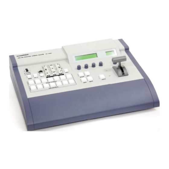
Product Overview The Datavideo SE-1000 is an HD / SD input, digital processing live video switcher. The SE-1000 includes 6 groups of video inputs (5 x HD/SD SDI - each with loop through, & 1 x DVI), and 3 x video outputs PGM ( 2 x HD/SD SDI &... -
Page 8: Packing List
Packing List The SE-1000 is shipped in two versions, if your SE-1000 is in an aluminium carrying case it is version B, if not it is version A: Version A 1. SE-1000 switcher x 1 2. BNC to BNC 14.5cm cable x 6 3. -
Page 9: Some General Notes On Installation
Finally, for examples of how to connect and integrate the SE-1000 into a variety of set ups, take a look at the brief Quick Start on page 9 and the more in depth explanations in Sample Applications on page 29. -
Page 10: Control Panel
SE-1000 from being accidentally switched off. Power and Alarm LEDs. The Power LED is lit when the SE-1000 is powered on. The Alarm LED will light up if there is a problem detected, for example if the fan has stopped running or the DC voltage has dropped. - Page 11 PGM / A bus crosspoint buttons 1 to 7. These buttons are used to select the PGM / A video source. If the SE-1000 is set to P/P (PGM/PST) mode, also known as flip-flop mode, then the PGM video signal is always selected here. If a button is illuminated Red it is Live, if it is illuminated Green it is Cued PST / B bus crosspoint buttons 1 to 7.
- Page 12 The LED indicators alongside the T Bar indicate which bus PGM/A or PST/B is live. The live bus is indicated by a green LED. During a transition both LEDs will be green, as both PGM/A and PST/B will be live until the transition is complete. Adjustment Knobs F1 - F4.
-
Page 13: Rear Panel
AUTO Take button (10). Each time a contact closure is executed the SE-1000 will automatically perform the designated transition. Ground / Earth Terminal. When connecting the SE-1000 to any other component, make sure that it is properly grounded by connecting this terminal to an appropriate point. When connecting, use the... - Page 14 Please refer to the section External Interfaces for more details. External Reference Input and BB Output Connecters (REF). An external sync signal can be fed into the SE-1000 via the REF In port. The external signal is looped through, so that it may be fed into other devices.
-
Page 15: Set Up
Set Up The SE-1000 is set up via various menus, which are displayed on the two LCD panels. The main LCD panel (15) displays all of the system settings, with the exception of the Format /Standard Converter Settings which are displayed in the DAC-40 LCD panel (14). -
Page 16: Set Up Menus
Set Up Menus To view other information and to change parameters we must first press the [FUNC] button. When the [FUNC] button is pressed it will illuminate green, as will one of the Wipe Pattern / Function Selector buttons. The first time the [FUNC] button is pressed on first boot up, the TIME button will be illuminated, (this corresponds to the example LCD panel on the previous page). -
Page 17: Menu 2/15 Dvi Input Mode
Set Up Menu 2/15 - DVI Input Mode Press the [FUNC] button, so that it is illuminated, and then press the [SET UP] button, so that it is also illuminated. Rotate Adjustment Knob F1 until DVIIN 2/15 is displayed The recommended screen resolutions for the DVI input are 1024 x 768 (XGA) and 1280 x 1024 (SXGA). The DVI input can be set to digital or analogue according to the type of signal you want to use. -
Page 18: Menu 3/15 Frame Synchroniser
Rotate Adjustment Knob F1 until FORMT 4/15 is displayed The SE-1000 can only be set to one format. It is not possible to combine SD and HD signals on different inputs. The format mode selected must match the format of the inputs being used. -
Page 19: Menu 5/15 Ref Internal / External Sync
Rotate Adjustment Knob F1 until REF 5/15 is displayed. The SE-1000 can be set to either internal or external synchronisation. If the SE-1000 is set to internal synchronisation it can cleanly switch asynchronous video inputs. In any of the external synchronisation modes a reference signal will be required. -
Page 20: Menu 6/15 Output Phase Adjustment
Menu 6/15 Output Phase Adjustment Press the [FUNC] button, so that it is illuminated, and then press the [SET UP] button, so that it is also illuminated. Rotate Adjustment Knob F1 until OUPHS 6/15 is displayed. The phase of the video output signals can be adjusted as follows: By rotating Adjustment Knob F2 you can choose between 0H or 1H: The output video signals are output to the system REF signal output in-phase. - Page 21 Phase Adjustment Set Up Diagram:...
-
Page 22: Menu 7/15 Ip Address Settings
Menu 7/15 IP Address Settings Press the [FUNC] button, so that it is illuminated, and then press the [SET UP] button, so that it is also illuminated. Rotate Adjustment Knob F1 until IP 7/15 is displayed. The default IP Address is 192.168.0.10. This can be adjusted if required. -
Page 23: Menu 9/15 Gw (Gateway) Settings
Menu 11/15 Bus Mode Settings The SE-1000 has two different bus modes, these affect the way the PGM/A and PST/B crosspoint buttons work. In A / B Mode the live output switches between crosspoint rail A (PGM) and crosspoint rail B (PST). Each time a transition or switch is performed the output will switch from A to B or B to A. -
Page 24: Backlight / Vanc / Bb 0 / 7.5 Ire
In P/P Mode (PGM / PST), often referred to as flip flop mode, the output will always be from the PGM/A crosspoint rail, and PST/B will always be the cued channel. Example: Before Transition A is RED During Transition A / B are RED After Transition A is RED To change the Bus Mode: Press the [FUNC] button, so that it is illuminated, and then press the [SET UP] button, so that it is also... -
Page 25: Menu 13/15 Dvi Phase / Position Settings
To leave the menu press the [FUNC] button so that it is no longer illuminated. Menu 14/15 INIT Init will return the SE-1000 to its factory default settings. Press the [FUNC] button, so that it is illuminated, and then press the [SET UP] button, so that it is also illuminated. -
Page 26: Xpt Menus
Rotate Adjustment Knob F1 until STATS 15/15 is displayed. ALM If the alarm LED has illuminated on the SE-1000, you should check this menu to see the cause, this could be the fan, a power fluctuation or both fan and power (F P). -
Page 27: Menu 2/3
Menu 2/3 XPTAS Assigning Crosspoints Press the [FUNC] button, so that it is illuminated, and then press the [XPT] button, so that it is also illuminated. Rotate Adjustment Knob F1 until XPTAS 2/3 is displayed. Rotate Adjustment Knob F2 to select the crosspoint (XPT) that you want to change. Rotate Adjustment Knob F3 to select the signal (SIG) that you want to assign. -
Page 28: Mem Menus
MEM Menus The SE-1000 can store up to 10 panel settings in the preset memory. The preset memory is flash memory, so it is stored even when the SE-1000 is switched off, or initialised (INIT). The following settings can be stored:... -
Page 29: Menu 2/3 Psmem Xpt Enable / Disable
Rotate Adjustment Knob F3 to select the number (NO.) of the preset that you wish to use (1 to 10). If any information is stored on a preset you will see an * next to the number. (In the example above *1 has stored information) To execute the command (STOR / RECL / CLR) press Adjustment Knob F4;... -
Page 30: Frz Menus Setting Freeze Frames
FRZ Menus Setting Freeze Frames Each of the video inputs on the SE-1000 can be set to freeze frame at any time. The freeze frame will be held as a still image. Menu 1/2 Freeze Frame Assignments The FRZ 1/2 display gives information about which crosspoints have freeze frames assigned. An * above the crosspoint number indicates that a freeze frame is assigned. -
Page 31: Cbgd Menus Setting The Background Colour
CBGD Menus Setting the Background Colour Menu 1/5 CBGD - Colour Background The CBGD Menu 1/5 allows you to set the colour of the background CBGD Menus 2/5 to 5/5 allow you to set four custom colours - USR1 to USR4 - these can be used in the EDGE, KEY, CBGD and WIPE Settings. -
Page 32: Key Menus Setting Up A Key
You will also need to set the CBGD to the USR number that you are adjusting. E.g. If you are adjusting USR1 you need to set the CBGD Colour to USR1 in order to see the colour background that you are adjusting on your output monitor. -
Page 33: Menu 1/7
Menu 1/7 Press the [FUNC] button, so that it is illuminated, and then press the [KEY] button, so that it is also illuminated. Rotate Adjustment Knob F1 until KEY 1/7 is displayed. Rotate Adjustment Knob F2 to select between LIN (Linear) or SELF keying. Linear uses the luminance signals of the selected Key Source. -
Page 34: Menu 3/7 Fill Key Fill
Menu 3/7 Fill Press the [FUNC] button, so that it is illuminated, and then press the [KEY] button, so that it is also illuminated. Rotate Adjustment Knob F1 until FILL 3/7 is displayed. Rotate Adjustment Knob F2 to select between BUS or COLR Will use the selected Key Fill video signal COLR Will use the selected colour as the Key Fill Rotate Adjustment Knob F3 to select the colour for the Key Fill. -
Page 35: Wipe Menus Setting Wipe Preferences
EDGE Menus 2/5 to 5/5 allow you to set four custom colours - USR1 to USR4 - these are the same settings that are used in KEY, CBGD and WIPE BODR Settings. Press the [FUNC] button, so that it is illuminated, and then press the [EDGE] button, so that it is also illuminated. -
Page 36: Menu 1/5 Bodr (Border) Settings
Menu 1/5 BODR (Border) Settings Press the [FUNC] button, so that it is illuminated, and then press the [WIPE] button, so that it is also illuminated. Rotate Adjustment Knob F1 until BODR 1/5 is displayed. Rotate Adjustment Knob F2 to adjust the border width. Rotate Adjustment Knob F3 to adjust the softness of the border. -
Page 37: Menu 2/5 Key Time Setting
Rotate Adjustment Knob F2 to adjust the transition time in seconds. Rotate Adjustment Knob F3 to adjust the transition time in frames. Rotate Adjustment Knob F4 to select the display mode. Time is displayed in Seconds and Frames. Time is displayed in Frames only. To leave the menu press the [FUNC] button so that it is no longer illuminated. -
Page 38: Format / Standard Converter Set Up
Format / Standard Converter Set Up The SE-1000 has six format / standard converters built in - See items 35 / 36 in the illustration on page 12. The converters can take HD / SD SDI and convert to HD / SD / YUV or Composite Video. You can use the converters to monitor your inputs on standard definition monitors, such as the Datavideo TLM 433. -
Page 39: Setting The Ire - Ntsc Standard Definition Only
Rotate the Adjustment Knob to select the format that you require, and then press the Adjustment Knob to save the setting. Once set the display will return to FN01. To Exit the set up menu rotate the Adjustment Knob anti clockwise until FN13 - EXIT is displayed and then press the Adjustment Knob. -
Page 40: Setting The Brightness
Setting the Brightness In standard definition mode you can adjust the brightness of each of the output channels. To adjust the brightness it is advisable to monitor the output on a screen. With the LCD displaying the status for channel 1, press the Adjustment Knob to bring up the Format Standard Converter Adjustment Menu, and rotate the Adjustment Knob until FN04 is displayed. -
Page 41: Setting Tint - Ntsc Composite Video Output Only
Rotate the Adjustment Knob to select YES and then press it to store the settings. Once stored the screen will display the new value. To Exit the set up menu rotate the Adjustment Knob anti clockwise until FN13 - EXIT is displayed and then press the Adjustment Knob. -
Page 42: Setting An Output To Colour Bar - Standard Definition Output Only
Setting an Output to Colour Bar Each of the output channels can be set to Colour Bars; this is an aid to setting up your monitors correctly. The colour bars are not available on High Definition Outputs. With the LCD displaying the status for channel 1, press the Adjustment Knob to bring up the Format Standard Converter Adjustment Menu, and rotate the Adjustment Knob until FN07 is displayed. -
Page 43: Checking Video In Format
Checking Video In Format Each converter automatically selects the Video Input Format according to the signal that it receives. You can check the format on the LCD panel. With the LCD displaying the status for channel 1, press the Adjustment Knob to bring up the Format Standard Converter Adjustment Menu, and rotate the Adjustment Knob until FN08 is displayed. -
Page 44: Resetting A Channel
Resetting a Channel Reset returns a converter channel to its factory default settings. With the LCD displaying the status for channel 1, press the Adjustment Knob to bring up the Format Standard Converter Adjustment Menu, and rotate the Adjustment Knob until FN11 is displayed. Press the Adjustment Knob and rotate it to select Yes or No, then press the Adjustment Knob again. -
Page 45: Monitoring
The format standard converter outputs are set to composite; and they are connected to two TLM-433 monitor banks. The optional Datavideo TB-10 Tally Box can provide tally indication to the TLM-433 monitor banks; there is a tally LED above each monitor. -
Page 46: Basic Operation
Basic Operation Switching The Live Output (PGM) is indicated by the Red Button on the Crosspoint Bus, to switch from one source to another simply press the required Crosspoint Button on the live bus. In this example PGM/A is the live bus, and Crosspoint 6 is the live channel. To switch to a different channel simply press one of the other Crosspoint Buttons on the PGM/A bus. -
Page 47: Performing A Transition Automatically (Using The Auto Button)
As the T-Bar is moved you will notice that both buses become live, this is because both sources are in use. When the T-Bar has fully traversed from top to bottom, or bottom to top, the SE-1000 will return to having one live bus and one cued bus. - Page 48 Press the AUTO button to effect the transition. You will see that the AUTO button is illuminated red during the transition, and that both buses become live. When the transition is complete the AUTO button light is extinguished and the SE-1000 will return to having one live bus and one cued bus.
-
Page 49: Performing A Key
Performing a Key Setting up a key is covered in KEY Menus - Setting up a Key on page 31 A key can be performed manually using the T-Bar or automatically using the AUTO button. The AUTO button will activate a key at the speed that has been set in the auto transition times menu. - (See TIME Menus - Setting Auto Transition Times page 35) In the following examples the KEY-S (Source) is a matte imported to F-MEM and assigned to XPT 1, the KEY-F (FILL) is a video source assigned to XPT 6, the live source is a video source assigned to XPT 7 and... - Page 50 To cancel the key effect push the T-Bar the other way, or press the AUTO Button, the output will return to the live source without key. The second way to perform a key effect is to use Key in conjunction with the Background (BKGD) button. Press the Key button and the Background (BKGD) button simultaneously, so that they are both illuminated.
-
Page 51: Assigning An Output To Auxiliary (Aux)
To cancel the key effect push the T-Bar the other way, or press the AUTO Button, the output will switch back to the live source without key. Assigning a signal to the Auxiliary Output The Auxiliary Output (AUX) can be assigned with any one of the seven crosspoints, the Preview (PVW), Program (PGM) or Clean (CLN) output. -
Page 52: Setting An Input Signal To Freeze Frame
Setting an input signal to Freeze Frame Any of the six input signals can be set to a freeze frame (still image). Press the [FUNC] button, so that it is illuminated, and then press the [FRZ] button, so that it is also illuminated. -
Page 53: Wiring Examples
On page 44 ( Monitoring ) there is an example of how to utilise the six built in Format / Standard converters for convenient monitoring of all the input channels. The two Datavideo TLM-433 3 x 4” TFT LCD Monitor Banks can be mounted above the SE-1000, together with the ITC-100, to form an extremely compact and space efficient set up. - Page 54 The ITC-100 is providing talkback communication between the crew and the director, and also tally light indication for the crew and talent. The PGM HD Component output is fed to the Datavideo TLM-170 17” HD Component monitor, while the PGM HD-SDI out is going to an HD Record Deck. The 6 inputs are being...
- Page 55 Wiring Examples In this example the SE-1000 is relying upon external sync, all the sources are connected to a signal generator, which is also connected to the SE-1000. The 4 cameras and playback VTR are connected using HD-SDI, and the laptop PC is connected using DVI.
-
Page 56: Image Transfer Software
One example of how this might be used is the import of a matte for use with the built in keyer. A simple black and white matte can be created on a PC and then imported into the SE-1000. You can also use it to save a still image from the SE-1000 to your PC, which you could then use to create a DVD sleeve. -
Page 57: Connecting The Se-1000 To A Pc
The SE-1000 can either be connected directly to a PC or it can be connected via a hub. If the SE-1000 is connected directly to a PC you must use a LAN crossover cable, if it is connected via a hub then use a straight LAN cable. - Page 58 Click on “Use the following IP address:” and enter the details as shown, this assumes that the SE-1000 has not been changed from its default values.
- Page 59 Your PC should now be ready to communicate with the SE-1000. Launch the SE-1000 Image Transfer Tool (imgTransfer.exe). You will see the IP Address at the bottom of the screen. The IP Address should match the SE-1000, which is 192.168.0.10. (In this example the IP address is 192.168.1.10 and therefore does not match)
-
Page 60: Setting The Format (Mode)
Setting the Format (Mode) It is important that the format of the image transfer tool matches the format that you have set the SE-1000 to, otherwise image transfers will fail. Click on the drop down arrow next to the Mode window and select the format you require. -
Page 61: Transferring An Image To The Se-1000
Click on the OK box to complete the process. Transferring an image from the SE-1000 To transfer an image from the SE-1000 to a PC you must first capture a still image to FMEM - see Page 28 FMEM Frame Memory for details To transfer the FMEM image to the PC click on Get Image, after a few seconds the image should appear. -
Page 62: Rs-422
RS-422 and GPI allow the SE-1000 to be controlled from an external device. Tally provides information about the status of each of the Input Channels. The Datavideo TB-10 is able to decode this data and feed tally information to tally lights, monitors such as the Datavideo TLM 433, or talkback systems such as the Datavideo ITC-100. -
Page 63: Gpi Connector
The GPI (General Purpose Interface) Connecter allows for a simple remote control to be added to the SE- 1000. A simple push button will emulate the Auto Button. Each time the button is pressed the SE-1000 will perform whatever transition is set. -
Page 64: Troubleshooting / Faq
Troubleshooting / FAQ No power If no lights are displayed on the SE-1000, when the power switch is in the On position, then there is no power or insufficient power, getting to the unit. Ensure that the power supply is connected to an appropriate AC mains outlet and that it is switched on. -
Page 65: Useful Accessories
TLM-433 / TLM-433JF Monitor Bank / Monitor Bank Holder The Datavideo TLM-433 3 x 4” TFT LCD monitor bank is an ideal monitoring bank for the SE-1000. Pictured above are 2 x TLM-433 which gives 6 x preview monitors, 5 for the input channels plus 1 for the AUX or PVW output. -
Page 66: Itc-100 8 Channel Talkback / Intercom
ITC-100 Talkback / Intercom System The ITC-100 is an ideal accessory for the SE-1000. It provides bi-directional communication between the camera crew and the control room, together with bi-colour tally light information down one cable. The TB-10 can provide tally information to the ITC-100, and the ITC-100 can then send the information to the ITC- 100SL belt packs, which each member of the camera crew would be wearing. -
Page 67: Specifications
Specification Video Processing - Video Format SD (480/59.94i - 576/50i) HD (1080/59.94i - 1080/50i - 720/59.94p - 720/50p) SDI/HD-SDI Specifications Standard SMPTE 259M-C (270Mbps - 525/625 Component Video) and SMPTE 292M (1.485/1.001 Gbps) Connector BNC (IEC 169-8) Impedance 75 Q Return Loss >... - Page 68 Output Formats Aspect Converter Input SD 16:9 or 4:3 Output SD 16:9 or 4:3 0 - 7.5 IRE Options (NTSC Only) Operating Temperature Humidity Power Dimensions (W x H x D) Weight 480/59.94i - 576/50i HD-YUV 1080/59.94i - 1080/50i - 720/59.94p - 720/50p 0°C to 40°C (32°F to 102°F) 10% to 90% (non condensing) DC 12V / 10A...
-
Page 69: Service And Support
It is our goal to make your products ownership a satisfying experience. Our supporting staff is available to assist you in setting up and operating your system. Please refer to our web site www.datavideo-tek.com for answers to common questions, support requests or contact your local office below.
Need help?
Do you have a question about the SE-1000 and is the answer not in the manual?
Questions and answers