Table of Contents
Advertisement
Quick Links
Advertisement
Table of Contents

Related Manuals for Advantech B+B SmartWorx LR77 v2


Summary of Contents for Advantech B+B SmartWorx LR77 v2
- Page 1 LTE Industrial Router LR77 v2 USER MANUAL...
- Page 2 GPL licence Source codes under GPL licence are available free of charge by sending an email to: cellularsales@advantech-bb.com. Advantech B+B SmartWorx s.r.o., Sokolska 71, 562 04 Usti nad Orlici, Czech Republic Manual Rev. 1 released in CZ, February 15, 2017...
-
Page 3: Table Of Contents
LR77 v2 Contents 1 Safety Instructions 2 WEEE directive 3 Router Description 4 Contents of Package 5 Router Design 5.1 Router versions ........5.2 Delivery identification . - Page 4 LR77 v2 7.1 Basic parameters ........7.2 Standards and regulations .
- Page 5 LR77 v2 List of Figures Contents of package ....... . . Front panel LR77 v2B(G) .
- Page 6 LR77 v2 List of Tables Router versions ........Delivery identification .
-
Page 7: Safety Instructions
LR77 v2 1. Safety Instructions Please, observe the following instructions: The router must be used in compliance with all applicable international and national laws and in compliance with any special restrictions regulating the utilization of the router in prescribed applications and environments. To prevent possible injury and damage to appliances and to ensure compliance with all relevant provisions, use only the original accessories. -
Page 8: Weee Directive
LR77 v2 2. Product Disposal Instructions The WEEE (Waste Electrical and Electronic Equipment: 2002/96/EC) directive was intro- duced to ensure that electrical/electronic products are recycled using the best available recov- ery techniques in order to minimize impact on the environment. This product contains high quality materials and components which can be recycled. -
Page 9: Router Description
LR77 v2 3. Router Description LTE router LR77 v is used to wirelessly connect various equipments and devices via Ether- net interface 10/100 to the Internet or Intranet. Thanks to high data transfer speed of up to 100 Mbit/s (download) and upload speed up to 50 Mbit/s it is an ideal wireless solution for traffic and security camera systems, individual computers, LAN networks, automatic teller machines (ATM) and other self-service terminals, etc. -
Page 10: Contents Of Package
LR77 v2 4. Contents of Package Basic delivered set of router includes: router, power supply, crossover UTP cable, up to three external antennas, clip for the DIN rail, paper start guide. Figure 1: Contents of package Temperature range for power supply is reduced to 0 C to +40 C! As optional accessories can also be supplied the following expansion ports (one for Basic version or two for Full version): RS232, RS485/422, MBUS, ETHERNET, CNT, SWITCH, WIFI, WMBUS or SDH. -
Page 11: Router Design
LR77 v2 5. Router Design 5.1 Router versions LR77 v2 router is supplied in the following versions (see table below). All versions are available in plastic or metal box according to customer requirements. Router versions Router Box LR77 v2B(G) Plastic LR77 v2B(G) SL Metal LR77 v2B L45... -
Page 12: Label Lr77 V2B
LR77 v2 5.2 Delivery identification Trade name Type name Other LR77 v2B(G) LR-77-v2 Basic version LR77 v2B(G) SL LR-77-v2 Basic version in the metal box LR77 v2F(G) LR-77-v2 Full version LR77 v2F(G) SL LR-77-v2 Full version in the metal box LR77 v2B L45 LR-77-v2 Basic version... -
Page 13: Ordering Codes For Basic Versions
LR77 v2 5.3 Order codes 5.3.1 Basic versions Expansion port Ordering code Version without expansion port LR77 v2B(G) / B L45 set Version with Ethernet expansion port LR77 v2B(G) / B L45 ETH set Version with RS232 expansion port LR77 v2B(G) / B L45 RS232 set Version with RS485 expansion port LR77 v2B(G) / B L45 RS458 set Version with MBUS expansion port... -
Page 14: Basic Dimensions Of Plastic Box (Bottom And Front View)
LR77 v2 5.4 Basic dimensions of the router box 5.4.1 Plastic box Figure 12: Basic dimensions of plastic box (bottom and front view) 5.4.2 Metal box Figure 13: Basic dimensions of metal box (bottom and front view) -
Page 15: Space Around Antennas (Plastic)
LR77 v2 5.5 Mounting recommendations possibility to be put on a work surface, DIN rail EN 60715 with included plastic or metal clip. For the most of applications with a built-in router in a switch board it is possible to recognize two kinds of environments: no public and industry environment of low voltage with high interference, public environment of low voltage without high interference. -
Page 16: Cable Routing (Plastic)
LR77 v2 For every cables we recommend to bind the bunch, we recommend for this use: – Length of the bunch (combination of power supply and data cables) can be maxi- mum 1.5 m. If the length of data cables exceeds 1.5 m or in the event of, the cable leads towards the switch –... -
Page 17: Default Position Of Din Holder
LR77 v2 5.6 Removing from the DIN rail DIN holder is suitable for DIN rail according to EN 60715 standard only. Default position of plastic or metal holder, which is used for mounting the router on a DIN rail, is shown in the following figure: Figure 20: Default position of DIN holder For removing from the DIN rail it is necessary to lightly push upward the router so that the... -
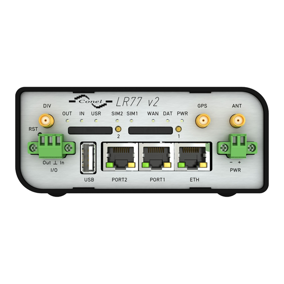
Page 18: Front Panel Lr77 V2F(G)
LR77 v2 5.7 Description of the front panel On the front panel is the following: Caption Connector Description 2-pin Connector for the power supply. RJ45 Connector for connection into the local computer network. PORT1 RJ45 Connector for expansion port RS232, RS458/422, MBUS, ETHERNET, CNT or SWITCH. -
Page 19: Status Indication
LR77 v2 5.7.1 Status indication About router status inform eight LED indicators on the front panel. ETH port, PORT1 and PORT2 have two additional LEDs that provide information about port status. Caption Color State Description Green Blinking Router is ready Starting of the router Fast blinking Updating firmware... -
Page 20: Power Connector
LR77 v2 5.7.2 Power connector PWR Panel socket 2-pin. Pin number Signal mark Description VCC(+) Positive pole of DC supply voltage (+9 to +36 V DC) GND(-) Negative pole of DC supply voltage Table 7: Connection of power connector Figure 23: Power connector Power supply for router is required between +9 V to +36 V DC supply. -
Page 21: Connecting Of The Antenna
LR77 v2 5.7.3 Antenna connector ANT, DIV and GPS (alternatively WIFI or WMBUS) Main and diversity antennas are connected to the router using the SMA connector on the front panel. Full version of the router also contains the third SMA antenna connector, through which the additional antenna can be connected (if WIFI expansion port is used, this connector is reverse –... -
Page 22: Ejected Sim Holder
LR77 v2 5.7.4 SIM card reader The SIM card reader for 3 V and 1,8 V SIM cards is placed on the front panel of the router. For getting the router to work is necessary to insert an activated SIM card with an unblocked PIN code. -
Page 23: Ethernet Connector
LR77 v2 5.7.5 Ethernet Port ETH Panel socket RJ45. Signal mark Description Data flow direction TXD+ Transmit Data – positive pole Input/Output TXD- Transmit Data – negative pole Input/Output RXD+ Receive Data – positive pole Input/Output — — — — RXD- Receive Data –... -
Page 24: Port1 Cable Connection
LR77 v2 5.7.6 PORT1 The PORT1 is equipped on customer’s request with one of the offered expansion ports: RS232 MBUS RS485 RS422 SWITCH (together with PORT2) ETHERNET Description and examples of expansion ports connection can be found in user’s guide for corresponding expansion port. -
Page 25: Port2 Cable Connection
LR77 v2 Plug cable for the second expansion port into the RJ45 connector labeled as PORT2 (see figure below). Figure 30: PORT2 cable connection 5.7.8 USB Port Panel socket USB-A. Signal mark Description Data flow direction +5 V Positive pole of 5 V DC supply voltage, 0.5 A USB data - USB data signal –... -
Page 26: O Connector
LR77 v2 Figure 32: I/O connector I/O user interface is designed for processing of binary input and control (setting) binary output. Binary output is not switched to ground in the default configuration. Maximum load binary output is 30 V / 100 mA. The constant current supplied by the binary input is 3 mA. Connect I/O cable into the I/O connector on the front panel of the router and tighten locking screws (see figure below). -
Page 27: Router Reset
LR77 v2 5.7.10 Reset When PWR LED starts flashing on the front panel, it is possible to restore the default con- figuration of the router by pressing the RST button on the front panel. After pressing this button the default configuration is restored and then router reboots (green LED will be on). For pressing the RST button could be used a narrow screwdriver. -
Page 28: First Use
LR77 v2 6. First Use 6.1 Connecting the router before first use Before putting the router into operation it is necessary to connect all components which are required to run your applications. Don’t forget to insert SIM card. The router can not operate without connected antenna, SIM card and power supply. If the antenna is not connected, router can be damaged. -
Page 29: Entering The Ip Address Of The Router
LR77 v2 6.2 Start The router is put into operation when the power supply is connected to this router. By default, the router will automatically start to log on to the default APN. DHCP server will start to assign addresses for devices on the Ethernet port ETH0. Router behavior can be changed via the web interface. -
Page 30: Router Web Interface
LR77 v2 After successfully entering login information user gains access to the router via his internet browser. Figure 39: Router web interface A detailed description of the router settings via the Web interface can be found in the document Configuration manual for v2 routers. 6.3.2 Configuration over Telnet For status monitoring, configuration and administration of the router can be also used Telnet. -
Page 31: Technical Parameters
LR77 v2 7. Technical Parameters 7.1 Basic parameters LR77 v2 Temperature range Operating -40 C to +75 C Storage -40 C to +85 C Humidity Operating 0 to 95 % relative humidity non condensing Storage 0 to 95 % relative humidity non condensing Altitude Operating 2000 m / 70 kPa... -
Page 32: Standards And Regulations
LR77 v2 7.2 Standards and regulations The router complies with the following standards and regulations. 7.2.1 Versions LR77 v2B and LR77 v2F Versions LR77 v2B and LR77 v2F Telecom and emission ETSI EN 301 511 v9.0.2, ETSI EN 301 908-1 v5.2.1, ETSI EN 301 908-2 v5.2.1, ETSI EN 301 908-13 v5.2.1 ETSI EN 301 489-1 v1.9.2 Safety... -
Page 33: Technical Parameters Of Module
LR77 v2 7.3 Technical parameters of module 7.3.1 Versions LR77 v2B and LR77 v2F LTE module for versions LR77 v2B and LR77 v2F LTE parameters Bit rate 100 Mbps (DL) / 50 Mbps (UL), UE CAT. 3 3GPP rel. 9 standard Supported bandwidths: 5 Mhz, 10 Mhz, 20 Mhz Supported frequencies: 800 / 900 / 1800 / 2100 / 2600 MHz HSPA+ parameters... -
Page 34: Lte Module Supports 450 Mhz
LR77 v2 Continued from previous page LTE module for versions LR77 v2BG and LR77 v2FG UMTS parameters PS bit rate 384 kbps (DL) / 384 kbps (UL) CS bit rate 64 kbps (DL) / 64 kbps (UL) W-CDMA FDD standard Supported frequencies: 900 / 1800 / 2100 MHz GPRS/EDGE parameters Bit rate 237 kbps (DL) / 59,2 kbps (UL) -
Page 35: Technical Parameters Of Gps
LR77 v2 7.4 Technical parameters of GPS GPS is not available when the router is equipped with the LTE module 450 MHz! GPS specifications Antenna 50 Ohms – active Protocols NMEA 0183 v3.0 Frequency 1575.42 MHz Sensitivity Tracking: -161 dBm Acquisition (Assisted): -158 dBm Acquisition (Standalone): -145 dBm Acquisition time... -
Page 36: Technical Parameters Of Processor
LR77 v2 7.5 Technical parameters of processor 32b ARM microprocessor Memory 512 Mb DDR SDRAM 128 Mb FLASH 1 Mb MRAM Interface Serial interface RS232 Ethernet interface 10/100 Mbit/s USB 2.0 interface Table 20: Technical parameters of processor 7.6 Technical parameters of I/O port Binary input and output Input/Output Binary input... -
Page 37: Recommended Literature
LR77 v2 8. Recommended Literature Advantech B+B SmartWorx: Start guide for v2 routers, Advantech B+B SmartWorx: Configuration manual for v2 routers, Advantech B+B SmartWorx: User’s manual – Expansion port RS232, Advantech B+B SmartWorx: User’s manual – Expansion port RS485/422, Advantech B+B SmartWorx: User’s manual –... -
Page 38: Troubleshooting
LR77 v2 9. Troubleshooting If you can not connect to the router from your PC, your network card may be configured the way it is not possible to connect to the router. Take one or more of the following steps to solve the problem: Select the communication rate 10 MB/s in the properties of your network card. - Page 39 LR77 v2 Ethernet connection fails or isn’t establishing. It is possible to turn auto negotiation off and set a rate and duplex manually on the Ethernet interface of the router. DynDNS doesn’t function. With private APN this is not functional. If the same IP address is recorded in your canonic name as dynamically assigned address, it means that the operator is using NAT or firewall.
-
Page 40: Customers Support
During cleaning of the router do not use aggressive chemicals, solvents and abrasive cleaners! Advantech B+B SmartWorx s.r.o. hereby declares that the router narrated in this user’s guide fits all basic demands of directive 1999/5/EC (R&TTE). Router fits values of coefficient SAR defined by association ICNIRP and values of "About protection of health before non-ionized radiation".
Need help?
Do you have a question about the B+B SmartWorx LR77 v2 and is the answer not in the manual?
Questions and answers