Advantech ICR-3201 Series User Manual
Lan industrial router
Hide thumbs
Also See for ICR-3201 Series:
- User manual (39 pages) ,
- Hardware manual (36 pages) ,
- Start manual (9 pages)
Table of Contents
Advertisement
Quick Links
Advertisement
Table of Contents

Subscribe to Our Youtube Channel
Related Manuals for Advantech ICR-3201 Series


Summary of Contents for Advantech ICR-3201 Series
- Page 1 LAN Industrial Router ICR-3201 USER MANUAL...
- Page 2 Website www.advantech-bb.com c 2020 Advantech Czech s.r.o. No part of this publication may be reproduced or transmitted in any form or by any means, electronic or mechanical, including photography, recording, or any information storage and retrieval system without written consent. Information in this manual is subject to change without notice, and does not represent a commitment on the part of Advantech.
- Page 3 Source codes under GPL licence are available free of charge by sending an email to: techSupport@advantech-bb.com. Please see http://ep.advantech-bb.cz/devzone for more information. Advantech Czech s.r.o., Sokolska 71, 562 04 Usti nad Orlici, Czech Republic Document No. MAN-0050-EN, revision from May 19, 2020. Released in the Czech Republic.
-
Page 4: Table Of Contents
ICR-3201 Contents 1 Safety Instructions 2 WEEE directive 3 Router Description 4 Contents of Package 5 Router Design 5.1 Router Versions ........5.2 Device Labels . - Page 5 ICR-3201 9 Troubleshooting 9.1 FAQ ......... . 10 Customers Support 10.1 Customer Support for NAM .
- Page 6 ICR-3201 List of Figures Version without WiFi ....... . . Version with WiFi .
- Page 7 ICR-3201 List of Tables Contents of package ....... . . Router versions .
-
Page 8: Safety Instructions
ICR-3201 1. Safety Instructions Please, observe the following instructions: The router must be used in compliance with all applicable international and national laws and in compliance with any special restrictions regulating the utilization of the router in prescribed applications and environments. To prevent possible injury and damage to appliances and to ensure compliance with all relevant provisions, use only the original accessories. -
Page 9: Weee Directive
ICR-3201 2. Product Disposal Instructions The WEEE (Waste Electrical and Electronic Equipment: 2012/19/EU) directive was in- troduced to ensure that electrical/electronic products are recycled using the best available recovery techniques in order to minimize impact on the environment. This product contains high quality materials and components which can be recycled. -
Page 10: Router Description
ICR-3201 3. Router Description ICR-3201 is a LAN industrial router intended for the global market. This router is an ideal device for the realization of a secure connection of two local area networks (LANs). Inter- connection is carried out using two ETHERNET 10/100 interfaces and secure tunnel (IPSec, OpenVPN, L2TP). -
Page 11: Contents Of Package
ICR-3201 4. Contents of Package The standard set of router includes items listed in the following table: Item# Description Figure Q’ty ICR-3201 or ICR-3201W router 1 pcs DIN holder 1 set (screwed on the router) Wing for wall mounting 2 pcs (screwed on the router) 2-pin terminal block for power supply 1 pcs... -
Page 12: Router Design
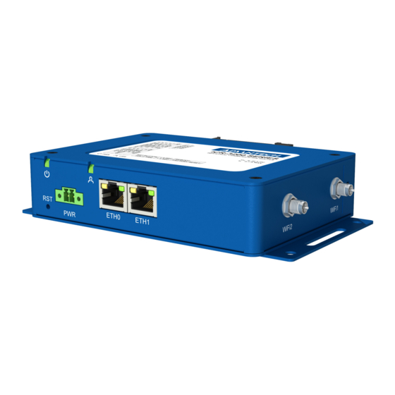
ICR-3201 5. Router Design 5.1 Router Versions ICR-3201 router is supplied in the following versions: Router versions Version without WiFi Version with WiFi Table 2: Router versions Figure 1: Version without WiFi Figure 2: Version with WiFi... -
Page 13: Labels Example
ICR-3201 5.2 Device Labels Figure 3: Labels example 5.3 Order Codes Order codes overview is shown in the table below. Product type Product name Order code Features – interfaces ICR-3200 ICR-3201 ICR-3201 LAN router, 2x ETH, 1x BI, 1x BO ICR-3200 ICR-3201 ICR-3201W... - Page 14 ICR-3201 5.4 Basic Dimensions of the Router Box (specified in mm) Figure 4: Basic dimensions of the router box Figure 5: Basic dimensions of the router box...
- Page 15 ICR-3201 5.5 Mounting Recommendations Router can be placed: on a flat surface, on a wall (or other surface) using the side wings, on a DIN rail EN 60715 with the included metal DIN rail clip. For most applications with a built-in router within a switchboard it is possible to recognize two kinds of environments: A non-public, industry environment of low voltage with high interference, A public environment of low voltage and without high interference.
-
Page 16: Default Position Of Din Rail Clip
ICR-3201 5.6 Removing from the DIN Rail The DIN rail clip is suitable for a DIN rail according to EN 60715 standard only. The default position of metal rail clip, which is used for mounting the router on a DIN rail, is shown in the following figure. -
Page 17: The Front Panel Of The Router
ICR-3201 5.7 Description of the Front Panel On the front panel of the router, there are located: Caption Connector Description — RST button used to restore the default configuration and re- boot the router 2-pin Terminal block for the power supply ETH0 RJ45 Ethernet connection to the computer network... -
Page 18: Power Connector
ICR-3201 5.7.2 Power Connector PWR Terminal block 3.5 mm. Pin number Signal mark Description VCC(+) Positive pole of DC supply voltage (+9 to +36 V DC) GND(-) Negative pole of DC supply voltage Table 6: Connection of power connector Figure 9: Power connector Power supply for router is required between +9 V to +36 V DC supply. -
Page 19: Ethernet Connector
ICR-3201 5.7.3 Ethernet Port ETH0 and ETH1 The panel socket of RJ45 is used for this interface. The insulation strength of Ethernet ports from each other and from the rest of the router (grounding) is 1500 V. Signal mark Description Data flow direction TXD+ Transmit Data –... -
Page 20: Router Reset
ICR-3201 5.7.4 Reset Button The RST button on the front panel has three functions on ICR-3200 routers: Reboot the router: Hold the RST button for less than 4 seconds, the router will be restarted. Factory reset – restore the default configuration: Hold the RST button for more than 4 seconds. -
Page 21: Overview Of Router Reboot And Reset
ICR-3201 Action Router behavior Trigger events – options Reboot Turns off and then turns on the router Disconnect and reconnect the power Send text reboot via SMS to SIM card number put in your router (your phone number has to be authorized –... -
Page 22: The Left Panel Of The Router
ICR-3201 5.8 Description of the Left Panel Interfaces located on the left panel are described in the table below. Caption Connector Description Grounding screw M3 screw Grounding screw (M3x6L) is connected to the ground of the board and to the negative pole of the power source. SERIAL | I/O 10-pin This connector has the RS232 and RS485 serial inter-... -
Page 23: Serial + I/O Connector
ICR-3201 5.8.1 Serial Interfaces and I/O Port The RS232 and RS485 serial interfaces together with the I/O interface are physically con- nected to the 10-pin panel socket. All three interfaces are not isolated from the router. The pinout of this conector is described in the tables below. Figure 15: Serial + I/O connector Signal mark Description... -
Page 24: Functional Scheme Of The Binary Interface
ICR-3201 The functional scheme of connection for the binary input and binary output is drawn on the picture below. Figure 16: Functional scheme of the binary interface... -
Page 25: The Right Panel Of The Router
ICR-3201 5.9 Description of the Right Panel Connectors located on the right panel are described in the table below. This panel has no connectors on it for the non-WiFi version of the router. Caption Connector Description WiFi2 R-SMA Connector for the second WiFi antenna. WiFi1 R-SMA Connector for the first WiFi antenna. -
Page 26: First Use
ICR-3201 6. First Use 6.1 Connecting the Router Before First Use Before putting the router into operation it is necessary to connect all of the components that are required to run your applications. 6.2 Start The router will start when a power supply is connected to the router. The DHCP server will start to assign addresses for devices connected through the Ethernet port ETH0. -
Page 27: Router Web Interface
ICR-3201 After successfully entering login information, the user will have access to the router web interface via their browser. Figure 20: Router web interface A detailed description of the router settings in the Web interface can be found in the Configu- ration manual for ICR-3200 routers. -
Page 28: Technical Parameters
ICR-3201 7. Technical Parameters 7.1 Basic Parameters Router parameters Temperature range Operating -40 C to +75 C Storage -40 C to +85 C Humidity Operating 0 to 95 % relative humidity non condensing Storage 0 to 95 % relative humidity non condensing Altitude Operating 2000 m / 70 kPa... -
Page 29: Standards And Regulations
ICR-3201 7.2 Standards and Regulations The router complies with the following standards and regulations: Standards and regulations Radio EN 301 893, EN 300 328 EN 301 489-1, EN 301 489-17, AS/NZS CISPR 32, FCC Part 15 Subpart B, ICES-003 Issue 6, EN 61000-6-2 Safety UL/EN/AS/NZS 62368-1 Transportation... -
Page 30: Type Tests And Environmental Conditions
ICR-3201 7.3 Type Tests and Environmental Conditions Phenomena Test Description Test levels EN 61000-4-2 Enclosure contact 6 kV (crit. A) Enclosure air 8 kV (crit. A) RF field AM EN 61000-4-3 Enclosure 10 V/m (crit. A) modulated (80 – 2700 MHz) 3 V/m (crit. -
Page 31: Technical Parameters Of Wifi
ICR-3201 7.4 Technical Parameters of WiFi WiFi Antenna connector 2x R-SMA – 50 (MU-MIMO) Supported WiFi bands 2.412 to 2.472 GHz, 5.180 to 5.825 GHz Standards IEEE: 802.11b, 802.11b+g, 802.11b+g+n, 802.11a, 802.11a+n, 802.11ac 2.4 GHz supported channels 1, 2, 3, 4, 5, 6, 7, 8, 9, 10, 11, 12, 13 5 GHz supported channels 36, 40, 44, 48, 149, 153, 157, 161, 165 Type of device... -
Page 32: Related Documents
ICR-3201 8. Related Documents Advantech Czech: Start Guide (QSG-0006-EN) Advantech Czech: ICR-3200 – Configuration Manual (MAN-0042-EN) Product related documents can be obtained on Engineering Portal at www.ep.advantech- bb.cz address. - Page 33 ICR-3201 9. Troubleshooting If you cannot connect to the router from your PC, your network card may be configured in such a way that it is not possible to connect to the router. Take one or more of the following steps in order to solve the problem: Make sure your PC’s network card is configured to obtain the IP address form the DHCP server (by default the DHCP server is running in the router).
- Page 34 ICR-3201 You can verify a Firewall by accessing remotely to the router’s Web interface. The operator may not provide the address of DNS server and without DNS server’s address it is impossible to connect to the dyndns.org server. The following mes- sages will be shown in the System Log: –...
- Page 35 During cleaning of the router do not use aggressive chemicals, solvents and abrasive cleaners! Hereby, Advantech Czech s.r.o. company declares that the radio equipment narrated in this user’s guide is in compliance with EU Directive 2014/53/EU. The full text of the EU Declaration of Conformity is available at the following internet address:...
Need help?
Do you have a question about the ICR-3201 Series and is the answer not in the manual?
Questions and answers