Advantech SmartFlex SR307 User Manual
Lte industrial router
Hide thumbs
Also See for SmartFlex SR307:
- User manual (61 pages) ,
- Start manual (20 pages) ,
- Start manual (20 pages)
Table of Contents
Advertisement
Quick Links
Advertisement
Table of Contents

Related Manuals for Advantech SmartFlex SR307


Summary of Contents for Advantech SmartFlex SR307
- Page 1 LTE Industrial Router SmartFlex SR307 USER MANUAL...
- Page 2 Website www.advantech-bb.com c 2016 Advantech B+B SmartWorx s.r.o. No part of this publication may be reproduced or transmitted in any form or by any means, electronic or mechanical, including photography, recording, or any information storage and retrieval system without written consent. Information in this manual is subject to change without notice, and does not represent a commitment on the part of Advantech B+B SmartWorx.
- Page 3 GPL licence Source codes under GPL licence are available free of charge by sending an email to: cellularsales@advantech-bb.com. Advantech B+B SmartWorx s.r.o., Sokolska 71, 562 04 Usti nad Orlici, Czech Republic Manual Rev. 1 released in CZ, November 4, 2016...
-
Page 4: Table Of Contents
SmartFlex SR307 Contents 1 Safety Instructions 2 WEEE directive 3 Router Description 3.1 Usage of the Router ....... . . - Page 5 SmartFlex SR307 7 Technical Parameters 7.1 Basic parameters ........
- Page 6 SmartFlex SR307 List of Figures Access to the Internet from LAN ......Backed up access to the Internet .
- Page 7 SmartFlex SR307 Binary output connection ......Router reset ........
- Page 8 SmartFlex SR307 List of Tables Router versions ........
-
Page 9: Safety Instructions
SmartFlex SR307 1. Safety Instructions Please, observe the following instructions: The router must be used in compliance with all applicable international and national laws and in compliance with any special restrictions regulating the utilization of the router in prescribed applications and environments. -
Page 10: Weee Directive
SmartFlex SR307 2. Product Disposal Instructions The WEEE (Waste Electrical and Electronic Equipment: 2002/96/EC) directive was intro- duced to ensure that electrical/electronic products are recycled using the best available recov- ery techniques in order to minimize impact on the environment. This product contains high quality materials and components which can be recycled. -
Page 11: Router Description
SmartFlex SR307 3. Router Description SmartFlex SR307 is an industrial cellular router designed for communication in mobile networks that make use of LTE, HSPA+, UMTS, EDGE or GPRS technology. The primary purpose of these routers is their use in the 450 MHz band whose main advantage is the long range. -
Page 12: Usage Of The Router
SmartFlex SR307 Examples of possible applications mobile office telemetric fleet management remote monitoring security system vending and dispatcher machines telematic 3.1 Usage of the Router The router is primarily intended for these four basic situations: I. Access to the Internet from LAN... -
Page 13: Backed Up Access To The Internet
SmartFlex SR307 II. Backed up access to the Internet (from LAN) Figure 2: Backed up access to the Internet III. Secure networks interconnection or using VPN Figure 3: Using VPN tunnel... -
Page 14: Serial Gateway
SmartFlex SR307 IV. Serial Gateway Figure 4: Serial Gateway... -
Page 15: Contents Of Package
SmartFlex SR307 4. Contents of Package Basic delivered set of router includes: router, power supply, crossover UTP cable, up to three external antennas, loose power and I/O connector (+8 pins 4-pins and 5-pins terminal block for RS485 and RS232 (only for version with interface RS232-RS485/422),... -
Page 16: Router Design
5. Router Design 5.1 Router versions SmartFlex SR307 router is supplied in the following versions (see table below). All versions are available in plastic or metal box according to customer requirements. All versions are available with PoE PD (Power over Ethernet – powered device) so you can power the router from both ETH0 and ETH1 interfaces, or with PoE PSE (power source equipment) so you can power other devices by the router. -
Page 17: Version Switch (Plastic)
SmartFlex SR307 Figure 10: Version SWITCH (plastic) Figure 15: Version SWITCH (metal) Figure 11: Version SWITCH and WiFi (plastic) Figure 16: Version SWITCH and WiFi (metal) Figure 12: Version RS232 (plastic) Figure 17: Version RS232 (metal) Figure 13: Version RS232-RS485 (plastic) Figure 18: Version RS232-RS485 (metal) Figure 14: Ver. -
Page 18: Delivery Identification
SmartFlex SR307 Figure 20: Version RS232-RS485-ETH (plastic) Figure 22: Version RS232-RS485-ETH (metal) Figure 21: RS232-RS485-ETH & WiFi (plastic) Figure 23: RS232-RS485-ETH & WiFi (metal) 5.2 Delivery identification Trade name Type name Other SmartFlex SR307 SmartFlex Router in a plastic or metal box Table 2: Delivery identification... -
Page 19: Order Codes
SmartFlex SR307 5.3 Order codes Order codes overview is shown in the table below. Product Name Order code Features – interfaces SR307 SR3070x0yz LTE module supports 450 MHz, 2x ETH, 1x USB, 2x BI, 1x BO, 1x microSD reader, 2x SIM reader... -
Page 20: Type Of Router Box
SmartFlex SR307 Letter "y" – type of the router box Type of box Number "y" in code Plastic Metal Table 5: Type of router box Letter "z" – type of the power supply connector Type of power supply Number "z" in code Europe UK &... -
Page 21: Basic Dimensions Of The Router Box
SmartFlex SR307 5.4 Basic dimensions of the router box Figure 25: Basic dimensions of the router box 5.5 Mounting recommendations It is possible to place the router on a flat surface, DIN rail EN 60715 with the included plastic or metal clip. -
Page 22: Removal Of The Din Rail
SmartFlex SR307 – The length of the bunch (combination of power supply and data cables) should be a maximum 1.5 m. If the length of data cables exceeds 1.5 m or if the cable is leading towards the switchboard, we recommend installing surge protectors. -
Page 23: Description Of The Rear Panel
SmartFlex SR307 5.7 Description of the rear panel The rear panel contains two holders for SIM cards (SIM1 and SIM2), a holder for microSD card (SD) and an RST button used to restore the default configuration and reboot the router. -
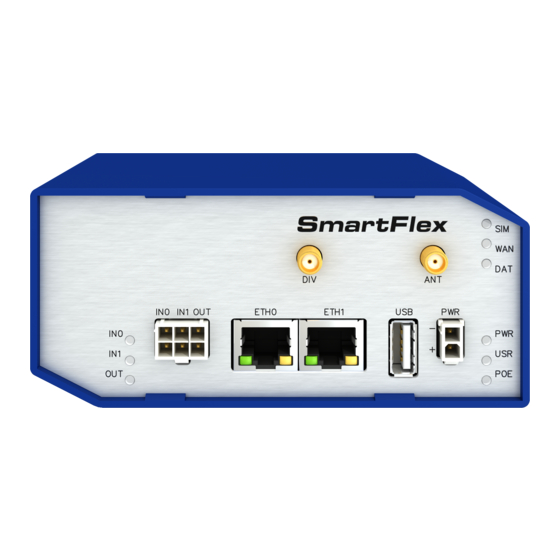
Page 24: Status Indication
SmartFlex SR307 5.8.1 Status indication There are nine LED indicators on the front panel to provide router status information. Each ETH port has two additional LEDs that provide information about the port status. Caption Color State Description Green Blinking Router is ready... -
Page 25: Power Connector Pwr
SmartFlex SR307 5.8.2 Power connector PWR Panel socket 2-pin. Pin number Signal mark Description GND(-) Negative pole of DC supply voltage VCC(+) Positive pole of DC supply voltage (+10 to +60 V DC) Table 10: Connection of power connector Figure 29: Power connector The power supply for the router must be between +10 V to +60 V DC supply. -
Page 26: Antenna Connector Ant, Div And Wifi
SmartFlex SR307 5.8.3 Antenna connector ANT, DIV and WiFi Main and diversity antennas are connected to the router using the SMA connector on the front panel. There is also available R-SMA antenna connector through which the additional antenna can be connected, if the router is equipped with WiFi module. -
Page 27: Sim Card Reader
SmartFlex SR307 5.8.4 SIM card reader Two SIM card readers for 3 V and 1.8 V SIM cards are located on the rear panel of the router. In order for the router to function, it is necessary to insert an activated SIM card with an unblocked PIN code. -
Page 28: Ethernet Ports (Eth0 And Eth1)
SmartFlex SR307 Changing the microSD card: Using the flat end of a spudger, or your fingernail, press the microSD card slightly into its slot until you hear a click. After hearing this click, release the card and it will pop out of its slot. -
Page 29: Power Over Ethernet (Poe)
SmartFlex SR307 The crossover UTP cable (Ethernet cable) plugs into the RJ45 connector labeled as ETH0 or ETH1 (see figure below). Figure 35: Connection of Ethernet cable The insulation strength of Ethernet ports from each other and from the rest of the router... -
Page 30: Poe Pse Usage
SmartFlex SR307 The PoE PD parameters can be found in Chapter 7.7. The POE LED on the front panel of the router lights up green when voltage is present in an Ethernet port so the user knows the router can be PoE powered. You can still power the router with this connector even if the router is powered with PoE (in PoE PD version), but the input voltage must be higher than 15 V DC. -
Page 31: Usb Port
SmartFlex SR307 5.8.8 USB Port Panel socket USB-A. Signal mark Description Data flow direction +5 V Positive pole of 5 V DC supply voltage, 0.5 A USB data - USB data signal – negative pole Input/Output USB data + USB data signal – positive pole... -
Page 32: Binary Inputs Connection
SmartFlex SR307 The I/O user Interface is designed for the processing of binary input and control (setting) of binary output. Binary output is open in the default configuration. The isolation strength is 1.5 kV. The pins are isolated from each other with the same strength. -
Page 33: Binary Output Connection
SmartFlex SR307 Binary output Binary output parameters: – 60 V AC / 300 mA – 60 V DC / 300 mA The current of the binary output is limited by a resettable fuse (300 mA). Binary output connection example: Figure 41: Binary output connection... -
Page 34: Reset
SmartFlex SR307 5.8.10 Reset When the PWR LED starts flashing on the front panel, it is possible to restore the de- fault configuration of the router by pressing the RST button on the rear panel. After pressing this button the default configuration will be restored and the router will reboot (after which the green LED will be on). -
Page 35: Interfaces Description
SmartFlex SR307 5.9 Interfaces Description Besides the basic version of SmartFlex router there are available versions with one of the following interfaces: RS232 interface RS232-RS485/422 interface SWITCH interface RS232-RS485-ETH interface 5.9.1 RS232 interface This interface is physically connected through the RJ45 connector. The RS232 converter is protected against bus overloads. -
Page 36: Rs232 Connector
SmartFlex SR307 Figure 44: RS232 connector Example of a meter connection to router: Figure 45: Meter connection to router State indication of RS232 interface: Description of indication Green LED Indicates receiving data Yellow LED Indicates transmitting data Table 19: State indication of RS232 interface Technical specification of RS232 bus (EN 1434):... -
Page 37: Rs232-Rs485/422 Interface
SmartFlex SR307 5.9.2 RS232-RS485/422 interface These interfaces are physically connected through the 5-pin and 4-pin terminal block con- nectors. The insulation strength is up to 2.5 kV. Attention, connectors are not isolated from each other! No state indication is displayed for this interface. These router versions comply with the standards and temperature ranges stated in Chap. -
Page 38: Rs485/422 Connector
SmartFlex SR307 Connection of RS422 connector: Signal Description Direction RxD- RS422 (-) Output RxD+ RS422 (+) Output TxD- RS422 (-) Input TxD+ RS422 (+) Input Table 23: Connection of RS422 connector Figure 48: RS485/422 connector The selection of either RS485 or RS422 can be performed by using jumpers on the board. -
Page 39: Switch Interface
SmartFlex SR307 Technical specification of RS232 and RS485 bus (EN 1434): RS232 and RS485 interface Max. operating RS232 bus current 15 mA Max. number of devices on RS485 bus (each 1,5 mA) Max. data rate 230400 bit/s on RS232 38400 bit/s on RS485 Max. -
Page 40: Rs232-Rs485-Eth Interface
SmartFlex SR307 Technical specification of Ethernet IEEE 802.3: Ethernet interface, IEEE 802.3 standard Maximum data rate 100 Mbit/s Max. total cable length (300 Bd, 200 nF/km) 100 m Table 26: SWITCH interface parameters 5.9.4 RS232-RS485-ETH interface This interface board includes a panel RJ45 connector for Ethernet connection (ETH2 in the figure), and four-pin and three-pin terminal block connectors for RS232 and RS485 con-... -
Page 41: Rs485 Connector
SmartFlex SR307 Figure 52: Ethernet connector Connection of RS485 connector: Signal Description Direction Signal ground — TxRx- RS485 B(-) Input/Output TxRx+ RS485 A(+) Input/Output Table 28: Connections of Terminal Block Connector RS485 Signal ground is isolated from the router’s ground. -
Page 42: State Indication Of The Rs232-Rs485-Eth Interface
SmartFlex SR307 State indication of the interface: Description of indication ETH2 – green LED Selected 100 Mbit/s Selected 10 Mbit/s ETH2 – Yellow LED The network cable is connected Blinking Data transmission The network cable is not connected RS485, RS232 – green LED Indicates Receive data RS485, RS232 –... -
Page 43: First Use
SmartFlex SR307 6. First Use 6.1 Connecting the router before first use Before putting the router into operation it is necessary to connect all of the components that are required to run your applications. Don’t forget to insert a SIM card. -
Page 44: Start
SmartFlex SR307 6.2 Start The router will start when a power supply is connected to the router. By default, the router will automatically start to log on to the default APN. The DHCP server will start to assign addresses for devices connected through the Ethernet port ETH0. These router behaviors can be changed via the web interface. -
Page 45: Router Web Interface
SmartFlex SR307 After successfully entering login information, the user will have access to the router web interface via their browser. Figure 58: Router web interface A detailed description of the router settings in the Web interface can be found in the... -
Page 46: Technical Parameters
SmartFlex SR307 7. Technical Parameters 7.1 Basic parameters SmartFlex Router Temperature range Operating -20 C to +60 C Storage -40 C to +85 C Cold start -15 C Data transfers via mobile network are available immediately -20 C Data transfers via mobile network are available approximately in five minutes after the start of... -
Page 47: Standards And Regulations
SmartFlex SR307 7.2 Standards and regulations The router complies with the following standards and regulations. Standards and regulations Telecom and emission ETSI EN 301 908-1 v6.2.1, ETSI EN 301 908-13 v6.2.1, ETSI EN 301-489-24 v1.5.1, ETSI EN 300 328 v1.8.1 ETSI EN 301 489-1 v1.9.2,... -
Page 48: Type Tests And Environmental Conditions
SmartFlex SR307 7.3 Type tests and environmental conditions Phenomena Test Description Test levels EN 61000-4-2 Enclosure contact 6 kV (crit. A) Enclosure air 8 kV (crit. A) RF field AM IEC 61000-4-3 Enclosure 20 V/m (crit. A) modulated (80 – 2700 MHz) -
Page 49: Technical Parameters Of Cellular Module
SmartFlex SR307 7.4 Technical parameters of cellular module Technical parameters of cellular module LTE parameters Bit rate 100 Mbit/s (DL) / 50 Mbit/s (UL), UE CAT. 3 3GPP rel. 9 standard Supported bandwidths: 5 Mhz, 10 Mhz, 20 Mhz Supported frequencies: 450 / 800 / 1800 / 2600 MHz... -
Page 50: Technical Parameters Of Wifi
SmartFlex SR307 7.5 Technical parameters of WiFi WiFi Antenna connector R-SMA – 50 Ohms Supported WiFi band 2.4 GHz, 5 Ghz Standards 802.11a, 802.11b, 802.11g, 802.11n 2.4 GHz supported channels 1, 2, 3, 4, 5, 6, 7, 8, 9, 10, 11, 12, 13... -
Page 51: Technical Parameters Of Power Over Ethernet (Poe)
SmartFlex SR307 7.7 Technical Parameters of Power over Ethernet (PoE) Standards IEEE 802.3at-2009 (PoE+) and IEEE 802.3af-2003 (PoE) are supported. Ca- bling needed is Category 5, up to 12.5 . It is possible to use a passive PoE injector. PoE PD: parameters for opposite PSE Input voltage range 42.5 –... -
Page 52: Recommended Literature
SmartFlex SR307 8. Recommended Literature Advantech B+B SmartWorx: Start Guide, Advantech B+B SmartWorx: Configuration Manual for SmartFlex Routers. -
Page 53: Troubleshooting
SmartFlex SR307 9. Troubleshooting If you can not connect to the router from your PC, your network card may be configured the way it is not possible to connect to the router. Take one or more of the following steps to solve the problem: Select the communication rate 10 MB/s in the properties of your network card. - Page 54 SmartFlex SR307 Ethernet connection fails or isn’t establishing. It is possible to turn auto negotiation off and set a rate and duplex manually on the Ethernet interface of the router. DynDNS doesn’t function. With private APN this is not functional.
-
Page 55: Customers Support
During cleaning of the router do not use aggressive chemicals, solvents and abrasive cleaners! Advantech B+B SmartWorx Company hereby declares that the router narrated in this user’s guide fits all basic demands of directive 1999/5/EC (R&TTE). Router fits values of coefficient SAR defined by association ICNIRP and values of "About protection of health before non-ionized radiation".
Need help?
Do you have a question about the SmartFlex SR307 and is the answer not in the manual?
Questions and answers