Advertisement
Table of Contents
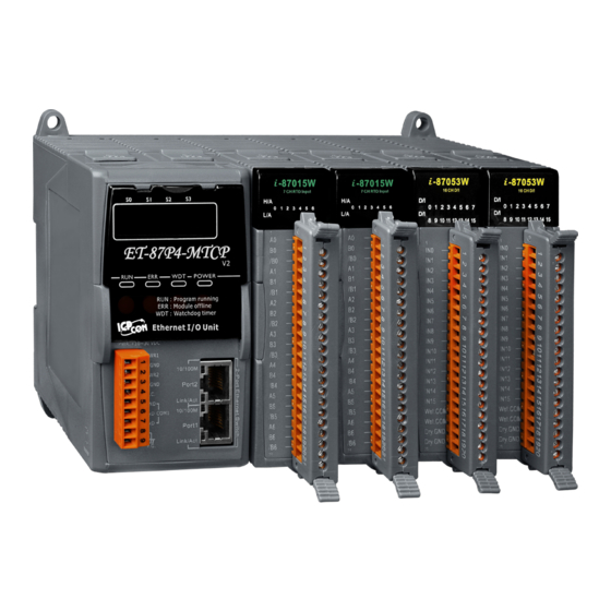
Congratulations on purchasing ET-8KPn-MTCP - a Modbus TCP I/O expansion unit to
expand I-87K series I/O modules and the most popular automation solution for remote
monitoring and control application. This Quick Start Guide will provide information
needed to get started. Please also consult the User Manual for detailed information on
the setup and use of ET-8KPn-MTCP.
In addition to this guide, the package includes the following items:
ET-8KPn-MTCP
(ET-8KP4-MTCP/ET-8KP8-MTCP)
●
ET-8KPn-MTCP Reference Document
CD:\Napdos\Modbus\ET87Pn\Document\
http://ftp.icpdas.com/pub/cd/8000cd/napdos/modbus/et87pn/document/
●
ET-8KPn-MTCP Website
http://www.icpdas.com/root/product/solutions/pac/ipac/et-87pn-mtcp.html
●
ICP DAS Website
http://www.icpdas.com/
Copyright © 2016 ICP DAS Co., Ltd. All Rights Reserved.
ET-8KP4-MTCP/ET-8KP8-MTCP
Software Utility CD
Quick Start
Dec. 2016, Version 1.0
Screw Driver
(1C016)
P. 1
1
Advertisement
Table of Contents

Subscribe to Our Youtube Channel
Related Manuals for ICP DAS USA ET-8KP4-MTCP


Summary of Contents for ICP DAS USA ET-8KP4-MTCP
- Page 1 ET-8KP4-MTCP/ET-8KP8-MTCP Quick Start Dec. 2016, Version 1.0 Congratulations on purchasing ET-8KPn-MTCP - a Modbus TCP I/O expansion unit to expand I-87K series I/O modules and the most popular automation solution for remote monitoring and control application. This Quick Start Guide will provide information needed to get started.
- Page 2 Mounting the Hardware The ET-8KPn-MTCP installation must provide proper ventilation, spacing, and grounding to ensure the equipment will operate as specified. A minimum clearance of 50mm between the ET-8KPn-MTCP and the top and bottom side of the enclosure panels must be provided.
- Page 3 Installing the Modbus Utility The Modbus Utility can be obtained from companion CD or ICP DAS FTP site: CD:\Napdos\Modbus\Modbus_Utility\ ftp://ftp.icpdas.com/pub/cd/8000cd/napdos/modbus/modbus_utility/ Using the Modbus Utility to Assign a New IP Address UDP Search of the Modbus Utility can be used to configure the IP address. Before starting the configuration process, ensure that the LAN1 are used to connect to network and make the controller under the running firmware mode.
- Page 4 Step 2: Configure IP Address i. Select the “Name” field i. Click the Name column of ET-8KPN-MTCP from the default IP address row ET-8KPn-MTCP ii. Click the Configuration (UDP) button ii. Click the Configuration (UDP) button to open the setting dialog iii.
- Page 5 Using the Modbus Utility to Configure the Module The Modbus Utility can be used to make the communication between the ET-8KPn-MTCP and PC/Laptop via the Modbus/TCP protocol. Step 1: Run the Modbus Utility and connect to ET-8KPn-MTCP i. Double-click the Modbus Utility shortcut on the desktop ii.
- Page 6 Step 2: Match the I/O module and then get the I/O configuration information i. Click the Refresh button to match the I/O modules to configuration of the controller i. Click the Refresh button ii. Select the About option from the Help menu to get the I/O configuration and firmware information iii.
- Page 7 Step 3: Set I/O configuration, get the I/O values and then save the I/O configuration i. Configure the I/O settings, such as Range Code, Power-on and Safe values ii. Select the Timer Interval from the Monitor menu to set the monitoring interval ii.
- Page 8 iii. Click the Monitor icon to start retrieving I/O values. The I/O values will be displayed in the Mapping tables iv. Select File option from the Save menu and select a location where the configuration file is about to be saved. This operation can save the controller configuration and I/O settings to an “ini”...
Need help?
Do you have a question about the ET-8KP4-MTCP and is the answer not in the manual?
Questions and answers